Chapter: Electric Energy Generation and Utilisation and Conservation : Solar Radiation and Solar Energy Collectors
Flat Plate Collector Efficiency Factor
Collector Efficiency
Factor
The heat lost from the collector can thus be calculated, if the
average plate temperature is known. However, this temperature is generally not
known. It will, therefore be necessary to consider the flow of heat in the
absorber plate and across the fluid tubes to the fluid so that the values of Tpm
can be related to the value of the inlet fluid temperature which is a known
quantity.
In
order to simplify the problem, the approach adopted will be to conduct the a
number of one- dimensional analysis. First, the one ŌĆō dimensional low of heat
in the absorber plate in a direction at right angles to the direction of fluid
flow will be considered. This will be followed by a consideration of the heat
flow from the plate to the fluid across the tube wall. Finally, the one ŌĆō
dimensional flow of fluid inside the tube will be analyzed.
Consider
a collector having an absorber plate of length L1 and width L2.
Assume that there are N fluid tubes and that the pitch of the tube is W = (L2/N).
Let Di and Do be the inside and outside diameter of the
tubes.
Consider
a section of the absorber plate with two adjacent fluid tubes. The temperature
in the plate(Tp) will vary in the x-direction in the manner as shown in Fig 4.27. It will be assumed
that the same distribution exists between any two tubes. Above the fluid tubes,
the temperature will be constant, while in between the tubes, temperature will
pass through the maximum. Taking a slice ŌĆśdyŌĆÖ along the flow direction and
neglecting heat conduction in the plate in that direction, we can write energy
balance for an element dx x dy of the plate.
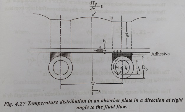
(Net
heat conducted into element) + (Incident energy absorbed) = ( Heat lost from
Element)
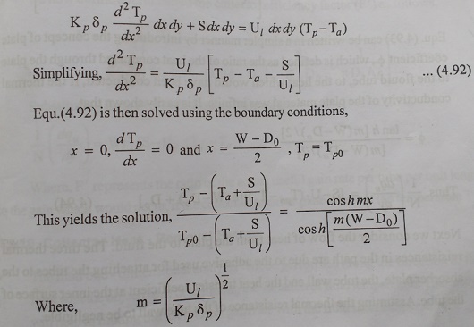
The
temperature distribution obtained is similar to that for a long rectangular
fin. The rate at which energy is conducted through the plate to one fluid tube
from both sides.
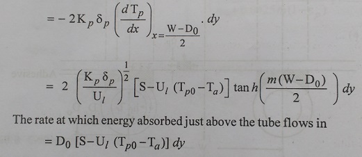
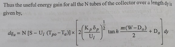
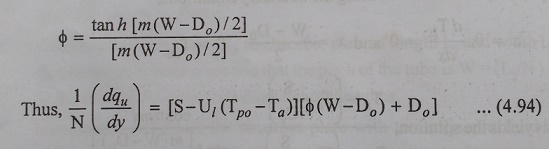
Equ.(4.93)
can be written in a simpler manner by introducing the concept of plate
coefficient ŽĢ, which is defined as the heat conducted through the plate to the
flouid tube, to the heat which would have been conducted, I the thermal
conductivity of the plate material was infinite. It is easily shown that,
Next
we consider the flow of heat from the plate to the fluid. The three thermal
resistances in the path are due to the adhesive used for attaching the tubes to
the absorber plate, the tube wall and the heat transfer coefficient at the
inner surface of the tube. Assuming the thermal resistance of the tube wall to
be negligible.
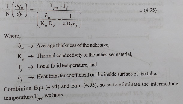
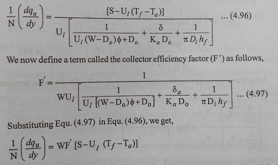
Where,
FŌĆś represents the ratio of the actual useful gain rate per tube per unit length
to the gain which would occur, if the collector absorber plate where at the
temperature Tf.
Related Topics