Chapter: Electric Energy Generation and Utilisation and Conservation : Solar Radiation and Solar Energy Collectors
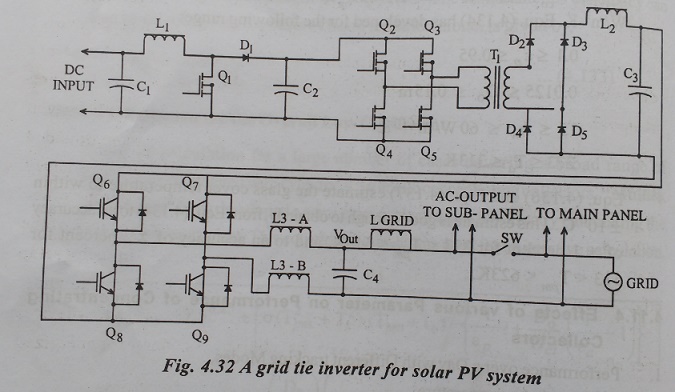
A Grid Tie Inverter for Solar PV System
A Grid Tie
Inverter for Solar PV System
Operating
a renewable energy system in parallel with an electric grid requires special
grid-interactive or grid tie inverters(GTI). The power processing circuits of a
GTI are similar to that of a conventional portable DC-AC converter that
operates as a stand-alone device. The main difference are in their control
algorithm and safety features. A GTI basically takes a variable voltage from a
DC source, such as solar panels array or a wind system, and inverts it to AC
synchronized with the mains. It can provide power to your loads and feed an
excess of the electricity into the grid. Depending on power and voltage levels,
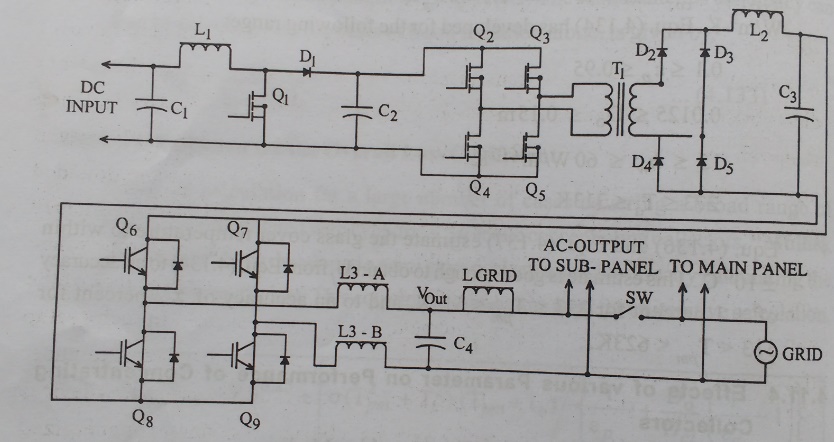
GTIs circuits normally have from one to three stages. A conceptual power train
schematic diagram below illustrates the principles of operation of a
three-stage grid tie inverter. Such a topology can be useful for low-voltage
input (such as 12V) in grounded systems. The control circuits and miscellaneous
details are not shown here. As I mentioned above, there are also two-stage and
single –stage configurations.
The
input voltage is first raised by the boost converter formed with inductor L1,
MOSET Q1, diode D1 and capacitor C2. If a PV array is rated for more than 50V,
generally one of the input direct current busses has to be grounded per
National Electric Code. The NEC however allows some exceptions which we will
discuss below. Although in theory either of two busses can be connected to
earth, usually it is a negative one. It is important to remember that if DC
input has a conduction pass to ground, the output AC conductors in
utility-interactive configurations should be isolated from DC. In our example,
a galvanic isolation is provided by a high frequency transformer in the second
conversion stage. This stage is a basically a pulse-width modulated DC-DC
converter. The schematic above shows a full bridge(also known as H-bridge)
isolating converter comprised of Q2-Q5, T1, D2-D5,L2 and C3. For power levels
under 1000 watt it could also be half-bridge or a forward converter (for more
details see SMPS types). Some commercial models use low-frequency (LF)
transformer in the output stage instead of a high frequency one in the DC-DC
section. With such a method, input is converted to 60Hz AC, and then a LF
transformer changes it to a required level and provides isolation at the same
time.
The
equipment with an LF transformer has a significantly larger weight and size,
but it will not inject a DC component into the load. Here is a lesser known
detail: UL 1741 does allow transormerless inverters and exampts them from
dielectric voltage withstand test between input and output. Therefore the
isolating stage can be eliminated. It is important to note that the conductors
from PV array in non-isolated design can’t be bounded to earth. NEC 690.41 allows
ungrounded configurations is they comply with Article 690.35. The
transformerless inverters of course feature lower weight and cost. They are
especially popular in Europe where ungrounded electrical systems are common.
However because of the lack of the galvanic isolation, these models present
potential electrical hazards. In such a setup if a person touches a terminal of
the PV panel or the battery, he will appear under AC line potential. The
transformerless system required additional protection devices per NEC Article
690.35 and special warning labels placed wherever energized circuits may be
exposed during service.
Related Topics