Chapter: Optical Communication and Networking : Fiber Optic Receiver and Measurements
Fiber diameter measurements
Fiber diameter measurements
1. Outer diameter
It is essential during the fiber manufacturing process (at the fiber drawing stage) that the fiber outer diameter (cladding diameter) is maintained constant to within 1%. Any diameter variations may cause excessive radiation losses and make accurate fiber–fiber connection difficult. Hence on-line diameter measurement systems are required which provide accuracy better than 0.3% at a measurement rate greater than 100 Hz (i.e. a typical fiber drawing velocity is 1 ms -1). Use is therefore made of noncontacting optical methods such as fiber image projection and scattering pattern analysis.
The most common on-line measurement technique uses fiber image projection (shadow method) and is illustrated in Figure 4.20. In this method a laser beam is swept at a constant velocity transversely across the fiber and a measurement is made of the time interval during which the fiber intercepts the beam and casts a shadow on a photodetector.
In the apparatus shown in Figure 4.20 the beam from a laser operating at a wavelength of 0.6328 μm is collimated using two lenses (G1 and G2). It is then reflected off two mirrors (M1 and M2), the second of which (M2) is driven by a galvanometer which makes it rotate through a small angle at a constant angular velocity before returning to its original starting position. Therefore, the laser beam which is focused in the plane of the fiber by a lens (G3) is swept across the fiber by the oscillating mirror, and is incident on the photodetector unless it is blocked by the fiber. The velocity ds/dt of the fiber shadow thus created at the photodetector is directly proportional to the mirror velocity df/dt following:
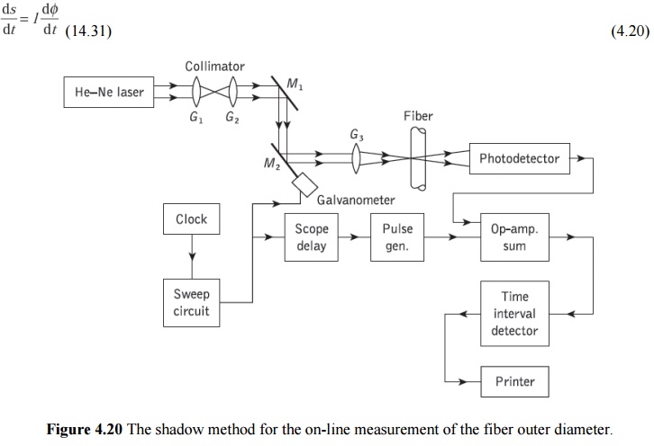
where l is the distance between the mirror and the photodetector. Furthermore, the shadow is registered by the photodetector as an electrical pulse of width We which is related to the fiber outer diameter do as:

Thus the fiber outer diameter may be quickly determined and recorded on the printer. The measurement speed is largely dictated by the inertia of the mirror rotation and its accuracy by the rise time of the shadow pulse.
Other on-line measurement methods, enabling faster diameter measurements, involve the analysis of forward or backward far-field patterns which are produced when a plane wave is incident transversely on the fiber. These techniques generally require measurement of the maxima in the center portion of the scattered pattern from which the diameter can be calculated after detailed mathematical analysis. They tend to give good accuracy (e.g. ±0.25 µm) even though the theory assumes a perfectly circular fiber cross-section. Also, for step index fibers the analysis allows determination of the core diameter, and core and cladding refractive indices. Measurements of the fiber outer diameter after manufacture (off-line) may be performed using a micrometer or dial gage. These devices can give accuracies of the order of ±0.5 µm. Alternatively, off-line diameter measurements can be made with a microscope incorporating a suitable calibrated micrometer eyepiece.
2. Core diameter
The core diameter for step index fibers is defined by the step change in the refractive index profile at the core–cladding interface. Therefore the techniques employed for determining the refractive index profile (interferometric, near-field scanning, refracted ray, etc.) may be utilized to measure the core diameter. Graded index fibers present a more difficult problem as, in general, there is a continuous transition between the core and the cladding.
In this case it is necessary to define the core as an area with a refractive index above a certain predetermined value if refractive index profile measurements are used to obtain the core diameter. Core diameter measurement is also possible from the near-field pattern of a suitably illuminated (all guided modes excited) fiber. The measurements may be taken using a microscope equipped with a micrometer eyepiece similar to that employed for off-line outer diameter measurements.
Related Topics