Chapter: Optical Communication and Networking : Fiber Optic Receiver and Measurements
Fiber cutoff wavelength measurements
Fiber cutoff wavelength
measurements
A
multimode fiber has many cutoff wavelengths because the number of bound
propagating modes is usually large. For example, considering a parabolic
refractive index graded fiber, the number of guided modes Mg is:

where a is the core radius and n1 and n2 are the core peak and cladding indices respectively. It may be
observed from Eq. (4.14) that operation at longer wavelengths yields fewer
guided modes. Therefore it is clear that as the wavelength is increased, a
growing number of modes are cutoff where the cutoff wavelength of aLPlm mode is the maximum wavelength for
which the mode is guided by the fiber.
Usually
the cutoff wavelength refers to the operation of single-mode fiber in that it
is the cutoff wavelength of the LP11 mode (which has the longest cutoff
wavelength) which makes the fiber single moded when the fiber diameter is
reduced to 8 or 9 μm. Hence the cutoff wavelength of the LP11 is the shortest
wavelength above which the fiber exhibits single-mode operation and it is
therefore an important parameter to measure.
The
theoretical value of the cutoff wavelength can be determined from the fiber
refractive index profile. Because of the large attenuation of the LP11 mode
near cutoff, however, the parameter which is experimentally determined is
called the effective cutoff wavelength, which is always smaller than the
theoretical cutoff wavelength by as much as 100 to 200 nm. It is this effective
cutoff wavelength which limits the wavelength region for which the fiber is
‘effectively’ single-mode.

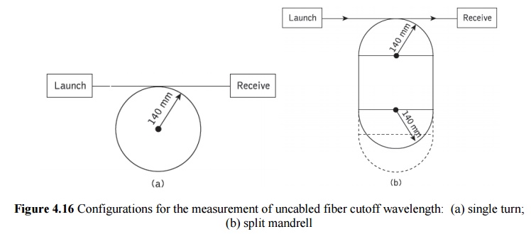
In the bending-reference technique the power Ps(λ) transmitted through the fiber
sample in the configurations shown in Figure 4.16 is measured as a function of
wavelength. Thus the quantity Ps(λ)
corresponds to the total power, including launched higher order modes, of the
ITU-T definition for cutoff wavelength. Then keeping the launch conditions
fixed, at least one additional loop of sufficiently small radius (60 mm or
less) is introduced into the test sample to act as a mode filter to suppress
the secondary LP11 mode without attenuating the fundamental mode at the
effective cutoff wavelength. In this case the smaller transmitted spectral
power Pb(λ) is measured which
corresponds to the fundamental mode power referred to in the definition. The
bend attenuation ab(λ) comprising the
level difference between the total power and the fundamental power is
calculated as:

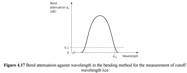
The bend
attenuation characteristic exhibits a peak in the wavelength region where the
radiation losses resulting from the small loop are much higher for the LP11
mode than for the LP01 fundamental mode, as illustrated in Figure 4.17.

It should
be noted that the shorter wavelength side of the attenuation maximum
corresponds to the LP11 mode, being well confined in the fiber core, and hence
negligible loss is induced by the 60 mm diameter loop, whereas on the longer
wavelength side the LP11 mode is not guided in the fiber and therefore,
assuming that the loop diameter is large enough to avoid any curvature loss to
the fundamental mode, there is also no increase in loss.
The
relative attenuation am(λ) or level
difference between the powers launched into the multimode and single-mode
fibers may be computed as:

Related Topics