Chapter: Optical Communication and Networking : Transmission Characteristics of Optical Fiber
Fiber couplers
Fiber couplers
An optical fiber coupler is a device that distributes light from a main fiber into one or more branch fibers.* The latter case is more normal and such devices are known as multiport fiber couplers. Requirements are increasing for the use of these devices to divide or combine optical signals for application within optical fiber information distribution systems including data buses, LANs, computer networks and telecommunication access networks.
Optical fiber couplers are often passive devices in which the power transfer takes place either:
(a) through the fiber core cross-section by butt jointing the fibers or by using some form of imaging optics between the fibers (core interaction type); or
(b) through the fiber surface and normal to its axis by converting the guided core modes to both cladding and refracted modes which then enable the power-sharing mechanism (surface interaction type).
Multiport optical fiber couplers can also be subdivided into the following three main groups, as illustrated in Figure 2.32.
1. Three- and four-port* couplers, which are used for signal splitting, distribution and combining.
2. Star couplers, which are generally used for distributing a single input signal to multiple outputs.
3. Wavelength division multiplexing (WDM) devices, which are a specialized form of coupler designed to permit a number of different peak wavelength optical signals to be transmitted in parallel on a single fiber.
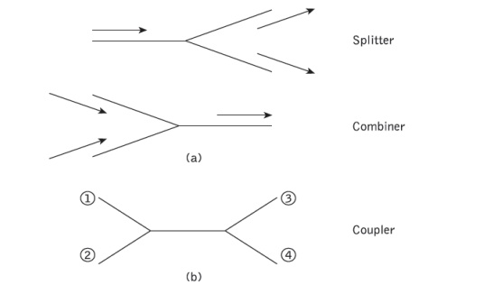
In this context WDM couplers either combine the different wavelength optical signal onto the fiber (i.e. multiplex) or separate the different wavelength optical signals output from the fiber (i.e. demultiplex). Ideal fiber couplers should distribute light among the branch fibers with no scattering loss† or the generation of noise, and they should function with complete insensitivity to factors including the distribution of light between the fiber modes, as well as the state of polarization of the light. Unfortunately, in practice passive fiber couplers do not display all of the above properties and hence the characteristics of the devices affect the performance of optical fiber networks.
* Four-port couplers may also be referred to as 2*2 star couplers.
† The scattering loss through the coupler is often referred to as the excess loss.
1. Three- and four-port couplers
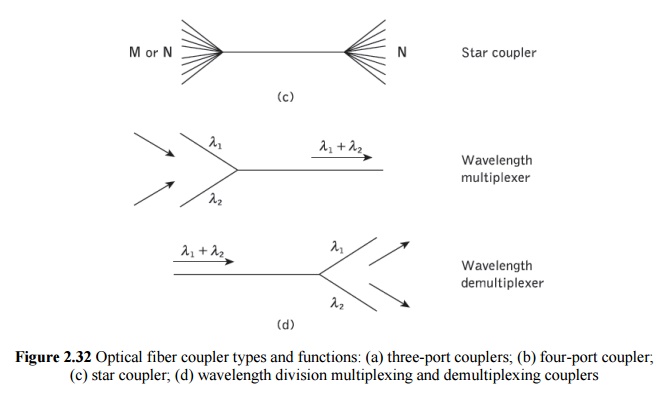
Several methods are employed to fabricate three- and four-port optical fiber couplers. The lateral offset method, illustrated in Figure 2.33(a), relies on the overlapping of the fiber end faces. Light from the input fiber is coupled to the output fibers according to the degree of overlap. Hence the input power can be distributed in a welldefined proportion by appropriate control of the amount of lateral offset between the fibers. This technique, which can provide a bidirectional coupling capability, is well suited for use with multimode step index fibers but may incur higher excess losses than other methods as all the input light cannot be coupled into the output fibers.
Another coupling technique is to incorporate a beam splitter element between the fibers. The semitransparent mirror method provides an ingenious way to accomplish such a fiber coupler, as shown in Figure 2.33(b). A partially reflecting surface can be applied directly to the fiber end face cut at an angle of 45° to form a thin-film beam splitter.
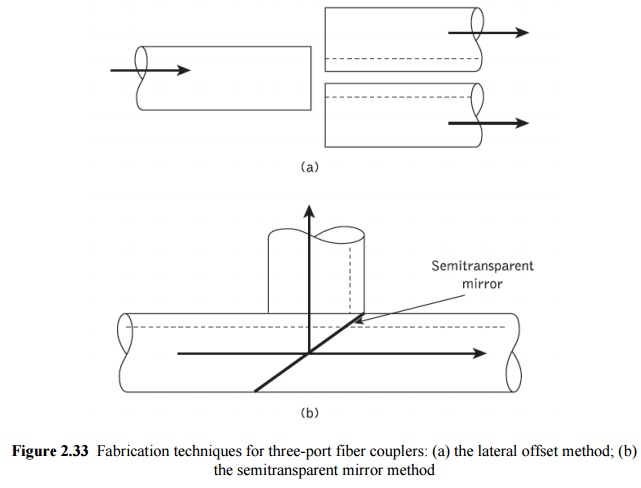
A fast-growing category of optical fiber coupler is based on the use of micro-optic components. In particular, a complete range of couplers has been developed which utilize the beam expansion and collimation properties of the GRIN-rod lens combined with spherical retro-reflecting mirrors. These devices, two of which are displayed in Figure 2.34, are miniature optical assemblies of compact construction which generally exhibit low insertion loss (typically less than 1 dB) and are insensitive to modal power distribution. Figure 2.34(a) shows the structure of a parallel surface type of GRIN-rod lens three port coupler which comprises two quarter pitch lenses with a semitransparent mirror in between. Light rays from the input fiber F1 collimate in the first lens before they are incident on the mirror. A portion of the incident beam is reflected back and is coupled to fiber F2, while the transmitted light is focused in the second lens and then coupled to fiber F3. The slant surface version of the similar coupler is shown in Figure 2.34(b).
The parallel surface type, however, is the most attractive due to its ease of fabrication, compactness, simplicity and relatively low insertion loss. Finally, the substitution of the mirror by an interference filter* offers application of these devices to WDM
Perhaps the most common method for manufacturing couplers is the fused biconical taper (FBT) technique. In this method the fibers are generally twisted together and then spot fused under tension such that the fused section is elongated to form a biconical taper structure. A three-port coupler is formed by removing one of the input fibers. Optical power launched into the input fiber propagates in the form of guided core modes.
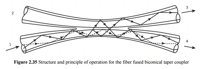
The higher order modes, however, leave the fiber core because of its reduced size in the tapered-down region and are therefore guided as cladding modes. These modes transfer back to guided core modes in the tapered-up region of the output fiber with an approximately even distribution between the two fibers. Often only a portion of the total power is coupled between the two fibers because only the higher order modes take part in the process, the lower order modes generally remaining within the main fiber. In this case a mode-dependent (and therefore wavelength-dependent) coupling ratio is obtained. However, when the waist of the taper is made sufficiently narrow, then the entire mode volume can be encouraged to participate in the coupling process and a larger proportion of input power can be shared between the output fibers. This strategy gives an improvement in both the power and modal uniformity of the coupler. The various loss parameters associated with four-port couplers may be written down with reference to Figure 2.35. Hence, the excess loss which is defined as the ratio of power input to power output is given by:
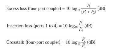
Finally, the splitting or coupling ratio indicates the percentage division of optical power between the output ports. Again referring to Figure 2.35:
2. Star couplers
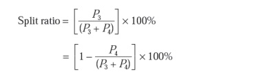
Star couplers distribute an optical signal from a single-input fiber to multiple-output fibers. The two principal manufacturing techniques for producing multimode fiber star couplers are the mixer-rod and the FBT methods. In the mixer-rod method illustrated in Figure 2.36 a thin platelet of glass is employed, which effectively mixes the light from one fiber, dividing it among the outgoing fibers. This method can be used to produce a transmissive star coupler or a reflective star coupler, as displayed in Figure 2.36. The typical insertion loss for an 8 * 8 mixer-rod transmissive star coupler with fiber pigtails is 12.5 dB with port-to-port uniformity of ±0.7 dB.
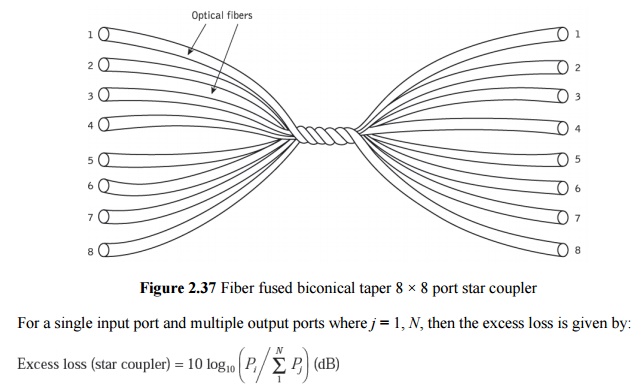
Thus the fibers which constitute the star coupler are bundled, twisted, heated and pulled, to form the device illustrated in Figure. 2.37. With multimode fiber this method relies upon the coupling of higher order modes between the different fibers. It is therefore highly mode dependent, which results in a relatively wide port-to-port output variation in comparison with star couplers based on the mixer-rod technique. In an ideal star coupler the optical power from any input fiber is evenly distributed among the output fibers. The total loss associated with the star coupler comprises its theoretical splitting loss together with the excess loss. The splitting loss is related to the number of output ports N following:
Related Topics