Chapter: Optical Communication and Networking : Transmission Characteristics of Optical Fiber
Fiber alignment and joint loss
Fiber alignment and joint loss
A major consideration with all types of fiber–fiber connection is the optical loss encountered at the interface. Even when the two jointed fiber ends are smooth and perpendicular to the fiber axes, and the two fiber axes are perfectly aligned, a small proportion of the light may be reflected back into the transmitting fiber causing attenuation at the joint. This phenomenon, known as Fresnel reflection, is associated with the step changes in refractive index at the jointed interface (i.e. glass–air–glass). The magnitude of this partial reflection of the light transmitted through the interface may be estimated using the classical Fresnel formula for light of normal incidence and is given by

where r is the fraction of the light reflected at a single interface, n1 is the refractive index of the fiber core and n is the refractive index of the medium between the two jointed fibers (i.e. for air n =1). However, in order to determine the amount of light reflected at a fiber joint, Fresnel reflection at both fiber interfaces must be taken into account. The loss in decibels due to Fresnel reflection at a single interface is given by:

Hence, using the relationships given in Eqs (2.59) and (2.60) it is possible to determine the optical attenuation due to Fresnel reflection at a fiber–fiber joint.
It is apparent that Fresnel reflection may give a significant loss at a fiber joint even when all other aspects of the connection are ideal. However, the effect of Fresnel reflection at a fiber–fiber connection can be reduced to a very low level through the use of an index-matching fluid in the gap between the jointed fibers. When the index-matching fluid has the same refractive index as the fiber core, losses due to Fresnel reflection are in theory eradicated. Unfortunately, Fresnel reflection is only one possible source of optical loss at a fiber joint. A potentially greater source of loss at a fiber–fiber connection is caused by misalignment of the two jointed fibers. In order to appreciate the development and relative success of various connection techniques it is useful to discuss fiber alignment in greater detail.
Any deviations in the geometrical and optical parameters of the two optical fibers which are jointed will affect the optical attenuation (insertion loss) through the connection. It is not possible within any particular connection technique to allow for all these variations.
Hence, there are inherent connection problems when jointing fibers with, for instance
ü different core and/or cladding diameters;
ü different numerical apertures and/or relative refractive index differences;
ü different refractive index profiles;
ü fiber faults (core ellipticity, core concentricity, etc.).
The losses caused by the above factors together with those of Fresnel reflection are usually referred to as intrinsic joint losses. The best results are therefore achieved with compatible (same) fibers which are manufactured to the lowest tolerance.
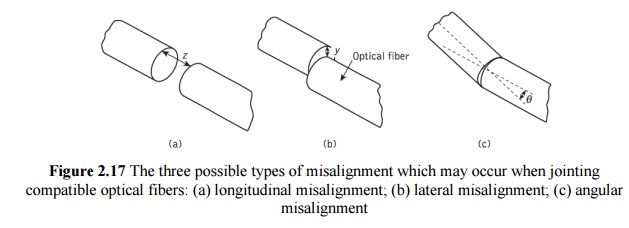
In this case there is still the problem of the quality of the fiber alignment provided by the jointing mechanism. Examples of possible misalignment between coupled compatible optical fibers are illustrated in Figure 2.17. It is apparent that misalignment may occur in three dimensions: the separation between the fibers (longitudinal misalignment), the offset perpendicular to the fiber core axes (lateral/radial/ axial misalignment) and the angle between the core axes (angular misalignment).
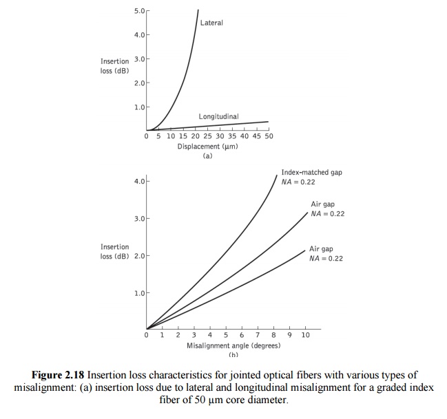
Optical losses resulting from these three types of misalignment depend upon the fiber type, core diameter and the distribution of the optical power between the propagating modes. Examples of the measured optical losses due to the various types of misalignment are shown in Figure 2.18. Figure 2.18(a) shows the attenuation characteristic for both longitudinal and lateral misalignment of a graded index fiber of 50 µm core diameter.
It may be observed that the lateral misalignment gives significantly greater losses per unit displacement than the longitudinal misalignment. For instance, in this case a lateral displacement of 10 µm gives about 1 dB insertion loss whereas a similar longitudinal displacement gives an insertion loss of around 0.1 dB. Figure 2.18(b) shows the attenuation characteristic for the angular misalignment of two multimode step index fibers with numerical apertures of 0.22 and 0.3. An insertion loss of around 1 dB is obtained with angular misalignment of 4° and 5° for the NA =0.22 and NA=0.3 fibers respectively.
It may also be observed in Figure 2.18(b) that the effect of an index-matching fluid in the fiber gap causes increased losses with angular misalignment. Therefore, it is clear that relatively small levels of lateral and/or angular misalignment can cause significant attenuation at a fiber joint. This is especially the case for fibers of small core diameter (less than 150 µm) which are currently employed for most telecommunication purposes.
1. Multimode fiber joints
Theoretical and experimental studies of fiber misalignment in optical fiber connections allow approximate determination of the losses encountered with the various misalignments of different fiber types. We consider here some of the expressions used to calculate losses due to lateral and angular misalignment of optical fiber joints. Longitudinal misalignment is not discussed in detail as it tends to be the least important effect and may be largely avoided in fiber connection.
Both groups of workers claim good agreement with experimental results, which is perhaps understandable when considering the number of variables involved in the measurement. Also, all groups predict higher losses for fibers with larger numerical apertures, which is consistent with intuitive considerations (i.e. the larger the numerical aperture, the greater the spread of the output light and the higher the optical loss at a longitudinally misaligned joint).
Theoretical expressions for the determination of lateral and angular misalignment losses are by no means definitive, although in all cases they claim reasonable agreement with experimental results. However, experimental results from different sources tend to vary (especially for angular misalignment losses) due to difficulties of measurement. It is therefore not implied that the expressions given in the text are necessarily the most accurate, as at present the choice appears somewhat arbitrary. Lateral misalignment reduces the overlap region between the two fiber cores. Assuming uniform excitation of all the optical modes in a multimode step index fiber, the overlapped area between both fiber cores approximately gives the lateral coupling efficiency µlat. Hence, the lateral coupling efficiency for two similar step index fibers may be written as
where n1 is the core refractive index, n is the refractive index of the medium between the fibers, y is the lateral offset of the fiber core axes, and a is the fiber core radius. The lateral misalignment loss in decibels may be determined using:

The predicted losses obtained using the formulas given in Eqs (2.61) and (2.62) are generally slightly higher than the measured values due to the assumption that all modes are equally excited. This assumption is only correct for certain cases of optical fiber transmission. Also, certain authors assume index matching and hence no Fresnel reflection, which makes the first term in Eq. (2.61) equal to unity (as n1/n = 1). This may be valid if the two fiber ends are assumed to be in close contact (i.e. no air gap in between) and gives lower predicted losses. Nevertheless, bearing in mind these possible inconsistencies, useful estimates for the attenuation due to lateral misalignment of multimode step index fibers may be obtained.
Lateral misalignment loss in multimode graded index fibers assuming a uniform distribution of optical power throughout all guided modes was calculated by Gloge. He estimated that the lateral misalignment loss was dependent on the refractive index gradient α for small lateral offset and may be obtained from:
A further estimate including the leaky modes gave a revised expression for the lateral misalignment loss given in Eq. (2.64) of 0.75(y/a). This analysis was also extended to step index fibers (where α = ∞) and gave lateral misalignment losses of 0.64(y/a) and 0.5(y/a) for the cases of guided modes only and both guided plus leaky modes respectively.
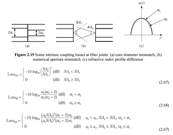
Factors causing fiber–fiber intrinsic losses were listed in previous Section; the major ones comprising a mismatch in the fiber core diameters, a mismatch in the fiber numerical apertures and differing fiber refractive index profiles are illustrated in Figure 2.19. Connections between multimode fibers with certain of these parameters being different can be quite common, particularly when a pigtailed optical source is used, the fiber pigtail of which has different characteristics from the main transmission fiber. Moreover, as indicated previously, diameter variations can occur with the same fiber type.
Assuming all the modes are equally excited in a multimode step or graded index fiber, and that the numerical apertures and index profiles are the same, then the loss resulting from a mismatch of core diameters (see Figure 2.19(a)) is given by:
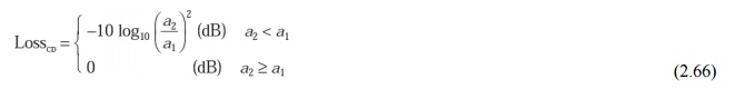
where a1 and a2 are the core radii of the transmitting and receiving fibers respectively. It may be observed from Eq. (2.66) that no loss is incurred if the receiving fiber has a larger core diameter than the transmitting one. In addition, only a relatively small loss (0.09 dB) is obtained when the receiving fiber core diameter is 1% smaller than that of the transmitting fiber.
When the transmitting fiber has a higher numerical aperture than the receiving fiber, then some of the emitted light rays will fall outside the acceptance angle of the receiving fiber and they will therefore not be coupled through the joint. Again assuming a uniform modal power distribution, and fibers with equivalent refractive index profiles and core diameters, then the loss caused by a mismatch of numerical apertures (see Figure 2.19(b))
2. Single-mode fiber joints
Misalignment losses at connections in single-mode fibers have been theoretically considered by Marcuse and Gambling et al. The theoretical analysis which was instigated by Marcuse is based upon the Gaussian or near-Gaussian shape of the modes propagating in single-mode fibers regardless of the fiber type (i.e. step index or graded index). Further development of this theory by Gambling etal. gave simplified formulas for both the lateral and angular misalignment losses at joints in single mode fibers. In the absence of angular misalignment Gambling et al. calculated that the loss Tl due to lateral offset y was given by:
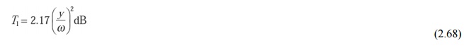
where ω is the normalized spot size of the fundamental mode.* However, the normalized spot size for the LP01 mode (which corresponds to the HE mode) may be obtained from the empirical formula:
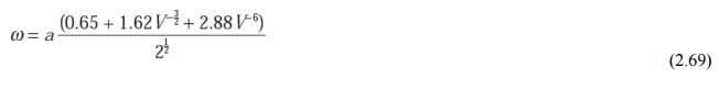
where w is the spot size in μm, a is the fiber core radius and V is the normalized frequency for the fiber. Alternatively, the insertion loss Ta caused by an angular misalignment q(in radians) at a joint in a single-mode fiber may be given by
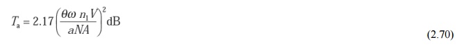
wheren1 is the fiber core refractive index and NA is the numerical aperture of the fiber. It must be noted that the formulas given in Eqs (2.69) and (2.70) assume that the spot sizes of the modes in the two coupled fibers are the same. Gambling et al. also derived a somewhat complicated formula which gave a good approximation for the combined losses due to both lateral and angular misalignment at a fiber joint. However, they indicate that for small total losses (less than 0.75 dB) a reasonable approximation is obtained by simply combining Eqs (2.68) and (2.70).
Assuming that no losses are present due to the extrinsic factors, the intrinsic coupling loss is given by
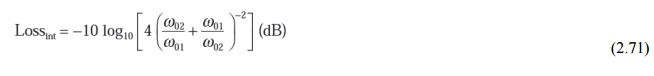
where w01 and w02 are the spot sizes of the transmitting and receiving fibers respectively. Equation (2.71) therefore enables the additional coupling loss resulting from mode-field diameter mismatch between two single-mode fibers to be calculated.
Related Topics