Chapter: 12th Computer Applications : Chapter 13 : Network Cabling
Ethernet Cabling Components
Ethernet
Cabling Components
Computer Networking is a group of interconnected
computers or other devices for sharing the data and resources among them.
Computers can be connected on the network with the help of wired media
(Unshielded Twisted pair, shielded Twisted pair, Co-axial cables and Optical
fibre) or wireless media (Infra Red, Bluetooth, WiFi)
Wireless networks enable more devices including
mobile sharing the resources and Internet connections remotely. But Compared to
wireless networks, wired networks maintain a faster Internet speed and more
secure. Wired networks for larger area are more expensive. Wired networks are
still used widely in the offices where need increased speed and secure connections
are very essential.
The computers with wired connections must be
configured with Ethernet cards. These cards enable the computers to have a
connection with other devices by using Ethernet cables. The switches and
routers may be used to increase the number of systems to be interconnected.
The Ethernet cable is the basic component of the
Local Area Network (LAN); here only one popular Ethernet wire is used - RJ45
Ethernet cable. We shall be discussing the different components used inside the
Ethernet cable. The components of the Ethernet cable are RJ45 connector, patch
cable (UTP cable), plastic covering. The RJ45 connector is made up of plastic
cubes connected at the both the ends. With this connector we will connect one
end at the computer and other end at the LAN port. The patch cables has eight
small wires inside. The plastic covering is used to provide protection to the
wires when it bends or get twisted while connecting to the system or to the LAN
port.
Ethernet cabling is the process of connecting the
computers with other devices using Ethernet cables. The four main components
used in the Ethernet cabling components are
1. Patch Cable (Twisted pair)
2. RJ45 Connector
3. Ethernet Ports
4. Crimping Tool
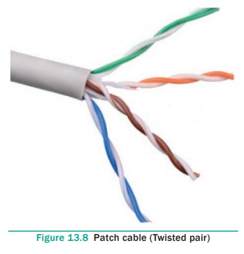
1. Patch Cable (Twisted Pair)
These Cables are generally made up of 8 wires in
different colors. Four of them are solid colours, and the others are striped.
The eight colors are white green, green, white orange, blue, white blue,
orange, white brown and brown. The following figure 13.8 shows the patch cable.
Ethernet cables are normally manufactured in
several industrial standards such as Cat 3, Cat 5, Cat 6, Cat 6e and cat 7.
“Cat” simply stands for “Category,” and the following number indicates the
version. Latest version denotes faster and higher frequencies, measured in Mhz.
Increasing the size of the cable also lead to slower transmission speed.
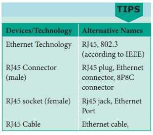
The cables together with male connectors (RJ45) on
each end are commonly referred as Ethernet cables. It is also called as RJ45
cables, since Ethernet cable uses RJ45 connectors
A crossover Ethernet cable is specially designed
for making a connection between two computers. Generally, the Ethernet cables
are designed to make a connection between a computer and a router or switch.
2. RJ45 Connector
The RJ45 connector is a small plastic cup which
will be used to connect the wire inside the connector and ready to connect the
Internet. The RJ45 connector looks similar like a telephone jack but it looks a
slightly wider. The Ethernet cables are sometime called as RJ45 cables. In RJ45
the “RJ” stands for the Registered Jack and the “45” simply refers to the
number of interface standard in the cable. See Figure 13.9
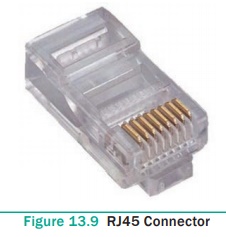
Each RJ45 connector has eight pins and connected to
each end of the Ethernet cable. since it has 8- position, 8-contact (8P8C)
modular plug, It is also known as 8P8C connector. These plugs (connector) are
then inserted into Ethernet port of the network card.
Wiring schemes and colour codes of the connector
The RJ45 connector has eight small jack inside to
connect eight small wires of the patch cable. The eight cables are in eight
different colors. Let’s discuss that eight colors and where does that eight
colors connect to the RJ45 connector.
Wiring schemes specifies how the wires to be
connected with RJ45 connector. There are two wiring schemes available to terminate the twisted-pair cable on each end,
which are T-568A and T-568B. The Table 13.1 describes the pinouts and colour
coding of these schemes.
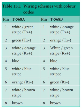
Although four pairs of wires are available in the
cable, Ethernet uses only two pairs: Orange and Green. The other two colors
(blue and brown) can be used ISDN or phone connections.
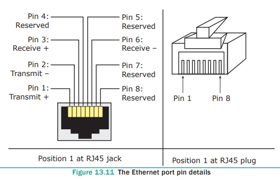
As we have already discussed about the pin details
in the Ethernet connector. Now let’s see the pin details of the Ethernet ports,
the pin 1 shows the transmission positive the pin 2 shows the transmission
negative the pin 3 shows the receiver positive. The pin 4 shows the reserved
position it is nothing but tells the connection for some other use. The pin 5,
7, 8 are also used in reserved position. The pin 6 shows the receiver negative.
The two main signals of the pins: the one is the TX which is transmission of
data and RX which is Receiver of data. See Figure 13.10 and Figure 13.11
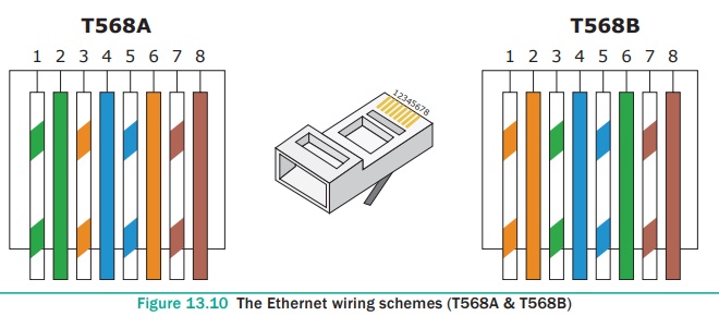
1. In the Figure 13.10 the position of pin no. 1
describes the transmit data or bidirectional, the bidirectional means it can be
sent to both connection with the TX (positive). The TX+ has positive terminal
and the color is used in this position is white green.
2. In the position of pin no. 2 describes the transmit data or bidirectional with the TX (negative). The TX- has negative terminal and the color is used in this position is Green.
3. In the position of pin no.3 describes the
receive data or bidirectional with the RX (positive). The RX is compatible to
receive the data which has positive terminal and the color is used in this
position is white orange.
4. In this position of pin no. 4 describes that it is not connected or bidirectional. It means there will be no transmitting or receiving will exist. But it can be used later for some other connection. The color used in this pin is blue.
5. In this position of pin no. 5 describes that it
is not connected or bidirectional and the color is white blue.
6. In this position of pin no. 6 describes the
receive data or bidirectional with the RX (Negative) which has a negative
terminal and the color used in this position is orange.
7. In this position of pin no. 7 describes that it
is not connected or bidirectional and the color is white brown.
8. In this position of pin no. 8 describes that it
is not connected or bidirectional and the color is brown.
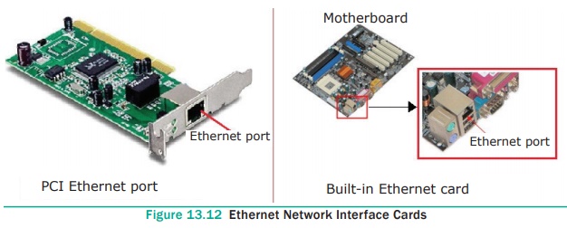
3. Ethernet card and Port
Ethernet card is a Network Interface Card (NIC)
that allows computers to connect and transmit data to the devices on the
network. It may be an expansion card or built-in type. Expansion card is a
separate circuit board also called as PCI Ethernet card which is inserted into
PCI slot on motherboard of a computer. Now a days most of the computers come
with built-in Ethernet cards which resides on motherboard. Wireless Ethernet
cards are also available, which uses radio waves to transmit data. See Figure
13.12
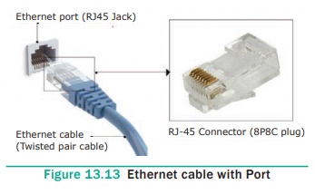
Ethernet port is an opening which is a part of an
Ethernet card. It accepts RJ45 connector with Ethernet cable. It is also called
as RJ45 jack. It is found on personal computers, laptops, routers, switches,
hubs and modems. We can see an Ethernet port on the back side of a computer or
a laptop. It connects Ethernet cable with Ethernet card mounted on motherboard.
These days, most of the computers and laptops have
a built-in Ethernet port for connecting the device to a wired network. Some of
them not having an Ethernet port use an Ethernet dongles to form a network with
other devices. Devices or computers which use wifi only for networking
eliminates both the cable and its port. See Figure 13.13
Once you inject the plug into the port the two led
lights will glow in the computer, one is green and another one is orange. The
orange light will start blinking which indicates that the Internet is
connected.
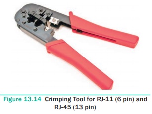
4. Crimping Tool
Crimping is the process of joining two or more pieces
of metal or wire by deforming one or both of them to hold each other. Joining
RJ45 connectorp together with twisted pair cable at each end is an essential
process in Ethernet cabling which lead the cable to function properly.
The crimping tool is a physical tool which is used
to connect the patch wire and the Ethernet connector. The crimping tool looks
like a small cutting handle with two mould of Ethernet port. The tool will
puncture the connector and inserts the wire set in the connector. See Figure 13.14
Crimping process for making Ethernet cables
1. Cut the cable with desired length
2. Strip the insulation sheath about 1 inch from
both end of the cable and expose the Twisted pair wires
3. After stripping the wire, untwist the smaller
wires and arrange them into the proper wiring scheme, T568B preferred
generally.
4. Bring the wires tighter together and cut them
down so that they all have the same length ( ½ inch).
5. Insert all the 8 coloured wires into the eight
grooves in the connector. The wires should be inserted until the plastic sheath
is also inside the connector.
6. Use the crimping tool to lock the RJ45 connector
on the cable. It should be strong enough to handle manual traction. Now it is
ready for data transmission.
7. Use a cable tester to verify the proper
connectivity of the cable. See Figure 13.15

History of ethernet
Bob Metcalfe invented
Ethernet in 1973 while at Xerox PARC (Palo Alto Research Center in
California, USA) and the company patented it in 1975. It was used for
interconnecting advanced computer workstations, making it possible to send data
to one another and to high- speed laser printers. Metcalfe and others then
finalized an open Ethernet standard
in 1980, and by 1985 it had become an IEEE standard. An industry was born, and Ethernet was ready for its meteoric
rise.
There have been a number of
networking standards published in the 802 branch of the IEEE, including the
802.3 Ethernet and 802.5 Token Ring standards. The IEEE standard was first
published in 1985 with the title IEEE
802.3 Carrier Sense Multiple Access with Collision Detection (CSMA/CD) Access Method and Physical Layer Specifications .
The IEEE standard does not use
“Ethernet” in the title, even though Xerox relinquished their trademark on the
Ethernet name. That’s because open standards committees are quite sensitive
about using commercial names that might imply endorsement of a particular
company. As a result, the IEEE calls this technology 802.3 CSMA/CD or just 802.3.
However, most people still use the Ethernet name when referring to the network
system described in the 802.3 standard.
Source : www.wikipedia.org
Related Topics