Chapter: Civil : Water Resources and Irrigation Engineering : Diversion and Impounding Structures
Diversion Head Works: Weir and Barrage
Diversion Head Works
It was
stated earlier that the main permanent canel, forming the primary part of a
direct irrigation scheme, takes off from a diversion weir or a barrage. In
fact, these permanent canals take off from rivers and the arrangements are so
well made at their heads, that a constant and a continuous water supply is
ensured into the canal, even during the periods of low flow. The works, which
are constructed at the head of the canal, in order to divert the river water
towards the canal, so as to ensure a regulated continuous supply of silt-free
water with a certain minimum head into the canal, are known as Diversion Head
works.
In general, the above purpose can be accomplished by constructing a barrier across the river, so as to raise the water level on the upstream side of the obstruction, and thus, to feed the main canals taking off from its upstream side at one or both of its flanks. The ponding of water can be achieved either only by a permanent pucca raised crest across the river or by a raised crest sup0plemnted by falling counter-balanced gates or shutters, working over the crest. If the major part or the entire ponding of water is achieved by a raised crest and a smaller part or nil part of it is achieved by the shutters, then this barrier is known as a weir [fig (a) and (b)]. On the other hand, if most of this ponding is done by gates and a smaller or nil part of it is done by the raised crest then the barrier is known as a Barrage or a River Regulator.
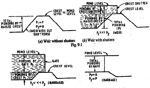
If most of the ponding or the entire ponding is done by a permanent raised crest, as a weir, then the afflux caused during high floods is quite high. On the other hand, if of the ponding is done b gates, as in a barrage, then gates can be opened high floods and the afflux (i.e. rise in HFL near the site) will be nil or minimum. Since, the latter device i.e. a barrage, gives less afflux and a better control upon the flow, because the inflow and outflow can be controlled to a much geater extent suitable manipulatios of its gates.
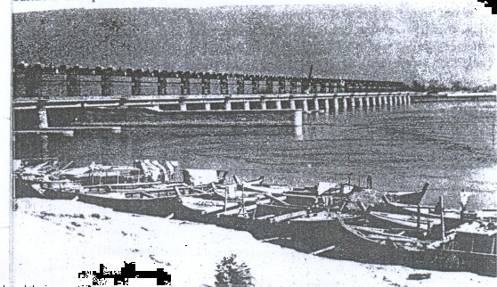
Figure: Photoview of a Barrage (Girija Barrage on Ghagra
river in U.P)
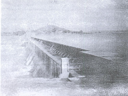
Figure: Photoview of a small height
dam like weir, provided with shutters at top of its solid crest (Devri Dam near
Jhansi in U.P.)
Moreover, a gate controller weir (i.e. a barrage) can be
provided with a roadway across the river at a small additional cost. The choice
between a weir shutters and one with counter-balanced gates (i.e. a barrage) is
largely a matter of cost and convenience in working. A shuttered weir will be
relatively cheaper but will lack the effective control possible in the case of
a barrage. Moreover, a barrage type construction can be easily supplemented
with a roadway across the river at a small additional cost. Hence, barrages are
almost invariably constructed these days on all important rivers.
Gravity and Non-Gravity Weirs
When the
weight of the weir (i.e. its body and floor) balances the uplift pressure
caused by the head of the water seeping below the weir, it is called a gravity
weir. On the other hand, if the weir floor is designed continuous with the
divide piers as reinforced structure, such that the weight of concrete slab
together with the weight of divided piers, keep the structure safe against the
uplift; the structure may be called as a Non gravity Weir. In the latter case,
RCC has to be used in place of brick piers, but in particular cases,
considerable savings may be obtained, as the weight of the floor can be much
less than what is required in a gravity weir.
Layout of a Diversion Head Works and its Components
A typical layout of a
canal head-works is shown in Fig. Such a head-works consists of:
(1) Weir proper.
(2) Under-sluices.
(3) Divided wall, dividing the river width into
two portions; one is called the weir portion, and the other portion from which
the canal take-sluice-pocket’ -sluices’or‘underor ‘weir scouring sluice from
each flank, then there will be two divide walls and two under sluices.
(4) River training works, such as marginal
bunds, guide banks, groynes, etc.
(5) Fish Ladder.
(6) Canal Head Regulator.
(7) Weir’s
ancillary works, such
as shutters, ga
(8) Silt Regulation Works.
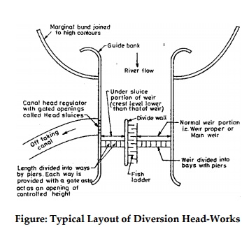
Figure: Typical Layout of Diversion
Head-Works
The
various parts of a diversion head-works schemes and their design considerations
are explained in details in the following pages.
The Diversion Weir and its Types. Alignment. As stated earlier, a
diversion weir or an anycut or an intake weir is a raised pucca
structure with or without shutters and laid across the river width. It is,
essentially, of a height say up to 9 metres or so. The height of shutters over
the weir crest seldom exceeds 1.2 metres or so. The entire length of the weir
is divided into a number of bays by means of divide piers so as to avoid
cross-flow in floods. As far as possible, the weir should be aligned at right
angle to the direction of the main river current. This ensures lesser length of
the weir, better discharging capacity and lesser cost. This right-angled
alignment is better and, therefore, common, especially, when the river bed is
silty or sandy. Sometimes, the weir may be aligned at an oblique angle to the
direction of the river current, and thereby, obtaining more safe and better
foundations. In such a case, the weir will be of greater length, will have less
discharging power and will be costlier. Moreover, due to non-axial flow, cross-currents
may be developed, which may undermine the weir foundation. An oblique alignment
may sometimes become necessary, when the river bed consists of gravel and
shingle, which could otherwise enter the head regulator of the main canal and
get deposited into the head reach of the main canal.
Types of Tank Weir and Their
Cross-sections.
Tank escape weirs are similar to
river-weirs (i.e. diversion weirs or anicuts), and hence, they may be
classified into the following three general types:
Type A: Masonry weirs
with a vertical drop;
Type B: Rockfill
weirs with a sloping apron; and
Type C: Masonry
weirs with a sloping masonary apron (glacis).
These three types of river weirs have
already been discussed in article.
Besides
these three important types of river weirs, which are used as tank weirs also,
the fourth type of a tank weir which is a combination of type A and type C, may
also be used. In such a D type weir, a number of vertical steps are made (as in
the case of a stepped fall) instead of providing a horizontal or sloping
downstream apron. Such weirs of type d are called weirs with stepped aprons.
The A and D type of weirs are most widely adopted, although every type of weir
has been used in Sourth Indian tanks.
The A type of weir i.e. weir with a masonary
pucca horizontal floor, may sometimes by provided with depressed floors, so as
to provide sufficient water-cushion for absorbing the impact of high water
falls. Typical sections of the two sub-types of A type, and D type of weirs,
and the conditions under which each is adopted are shown in figs. (a) (b), and
respectively.
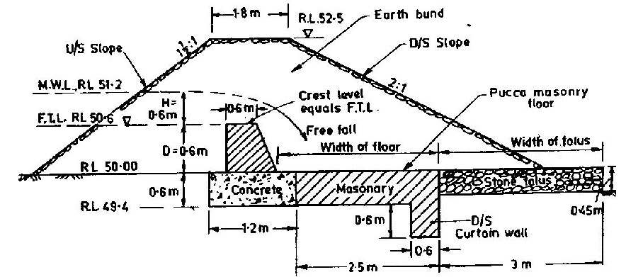
Figure:
(a) A typical masonry tank weir with a vertical drop, with a horizontal under
pressed floor, suitable for low drops of 0.6 to 0.9 metre or for even higher
drops when the soil is a rock.
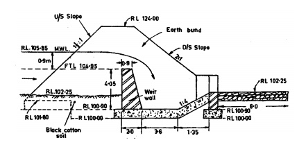
Figure: (b) A typical masonary tank weir with a vertical
drop with depressed floor, suitable for high drop (say 2.5 m upward) or in soft
soils but only slightly pervious.
The
general principles and considerations which guide the design of tank weir
sections, are the same as in the case of river weirs founded on rocks or loose
pervious or impervious soils But in case of tanks, the conditions regarding the
nature of foundation soil and the working conditions are more varied than in the
case of river weirs.
Say for
example, the river weirs or anicuts are generally founded on soft sandy soils,
whereas in tank weirs, almost every class of soils is occasionally to be built
on, except this rarely met foundation sand.
Similarly, the tail water conditions in anicuts
differ from those in tank weirs. This is because, the tail water backing up
during floods and affording some protection to the talus and to the soil at the
downstream toe of the apron, are absent in the majority of tank weirs; and,
therefore, the tank weirs built on soft oil would, other things being equal, be
more exposed to damage by scour at the downstream toe of the apron and
retrogression of levels than river weirs.
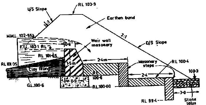
Figure A typical stepped-apron tank-weir suitable for
sites on soft soil when the drop exceeds 0.9 metre.
On the
other hand, the depth of water passing over the crests of tank weirs is
generally far less than that over anicuts, and in the case of very many tanks,
it is only, on an average, for a few days each year, that any flow at all
passes over the weir, and while the duration of continuous heavy flow is
frequently limited to a maximum of two to three days. Tank weirs are, thus,
usually worked, far less heavily and far less continuously than anicuts, and
this fact may be duly considered while designing them.
Empirical
Formulas for Determining Width of Floors of Tank Weirs. The width of the
horizontal floors of type A and D weirs, from the foot of the drop wall to the
downstream edge of the floor should never be less than 2 (D + H) where D is the
height of the drop wall, and H is the maximum water head over the wall. In
important works, this width may be increased to 3 (D + H). The rough stone apron
forming a talus below the last curtain wall may be of varying widths depending
on the nature of the soil and the velocity and annual probable quantity and
intensity of runoff ; it would generally vary from 2.5 (D + H) according to
varying conditions.
Related Topics