Chapter: Civil : Water Resources and Irrigation Engineering : Diversion and Impounding Structures
Canal Head Regulator
CANAL HEAD REGULATOR
A canal head regulator is required to serve the following
function:
(i) To regulate the discharge into the
off taking canal, functions:
(ii)To control the entry of sediment into the canal, and
The head regulator is usually aligned
at an angle of 900 to 1100 (figure) to the barrage axis
(5) . This orientation minimizes
entry of sediment into the off taking canal and prevent backflow and stagnation
zones in the under sluice pocket upstream of the regulator. The discharge
through the regulator is controlled by gates. Steel gates of 6 to 8 m spans are
generally used. However, larger spans can also be used in which case the gates
are operated by electric winches.
The pond level in the under sluice pocket, upstream of the canal head regulator, is obtained by adding the working head of about 1.0 to 1.2 m to the designed full supply level of the canal The level of the crest of the head regulator is obtained by subtracting from the pond level, the head over the crest required to pass the full supply discharge in the canal at the specific pond level. The crest of the regulator is always kept higher than the cill of the under sluice to prevent entry of sediment into the canal. If a sediment excluder is also provided in the under sluice pocket, the level of the crest of the head regulator should be decided keeping in view the design requirements of the sediment excluder in addition to the requirements of waterway, and the working head available.
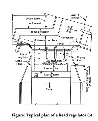
Figure: Typical plan of a head
regulator (6)
The width
of waterway in the canal head regulator should be such that the canal can be
its full supply with about 50 per cent of the working head provided (4). If the
required width of waterway at the ahead regulator is more than the bed width of
the canal, a converging insertion is provided downstream of the regulator to
attain the required canal width. The required head over the crest, H, for
passing a discharge Q with an overall waterway L is irked out from Eq.
The
height of the gates is equal to the difference of the pond level and the crest
level of regulator. But during high floods, the water level in the river would
be much higher than pond level, and the flood water may spill over the gates.
It would, obviously, be very economical to provide gates up to the HFL. Besides
the cost of heavier gates, the machinery required to operate them under large
water pressures would also be expensive. To prevent such spilling of flood
water into the canal, an RCC breast wall between the pond and HFL, and spanning
between adjacent piers is always provided. With this provision, gate opening
between the crest level and pond level is fully open which the gate is raised
up, i.e., up to the pond level. The opening is fully closed when the gate is
lowered to the crest the regulator.
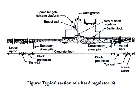
Figure: Typical section of a head
regulator (6)
Once the
crest level, waterway, number of spans, and thickness of piers have been fixed,
he head regulator is designed using the principles of weir design. The canal is
generally kept used when the highest flood passes through the river. This,
obviously, would be the worst attic condition and, hence, the floor thickness
must be able to resist uplift pressures under its condition. The exit gradient
for this condition should also be within safe limits. For economic reasons, the
floor is designed such that it can support the uplift pressure by its weight
and also be bending strength. For this purpose, the piers may have to be
extended up to the floor to provide necessary support to the upward bending
slab.
In the
jump trough region, the worst condition of uplift may occur when some discharge
passing into the canal. The safety of this part of the floor should. Therefore,
be checked for efferent discharges including the maximum one also. The
extension of the concrete floor upstream of the under sluices up to the end of
the head regulator also reduces the uplift pressures the downstream floor of
the regulator.
A bridge
and a working platform (for the operation of gates) are also constructed across
he head regulator.
Thus, CampDobbin’s methodSummer’smethodandgive matching
results.
For w/ u *=1.4 , Figure gives
K = 0.08 and ho = 57%
Therefore, Eq. gives
h = h o (1eKL/D ) = 57(1e-0.08´40/
3 )= 37.38%
Thus the
method proposed by Garde et al. gives relatively smaller value of hfor the
given problem compared to the value of h obtained by either CampDobbins
method o method.
Related Topics