Chapter: Electronic Devices and Circuits : Multistage Amplifiers and Differential Amplifier
Differential Mode Operation - Differential Amplifier
Differential Mode Operation
In the differential mode, the two input signals
are different from each other. Consider the two input signals which are same in
magnitude but 180" out of phase. These signals, with opposite phase can be
obtained from the center tap transformer. The circuit used in differential mode
operation is shown in the Fig..
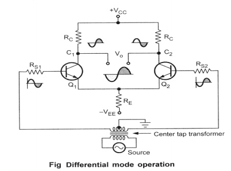
Assume that the sine wave on the base of Q 1is
positive going while on the base of Q 2 is negative going. With a
positive going signal on the base of Q 1, m amplified negative going
signal develops on the collector of Q1. Due to positive going
signal, current through R E also increases and hence a positive
going wave is developed across R E. Due to negative going signal on
the base of Q2, an amplified positive going signal develops on the
collector of Q 2. And a negative going signal develops across R E,
because of emitter follower action of Q 2. So signal voltages across
R E, due to the effect of Q1 and Q2 are equal
in magnitude and 180o out of phase, due to matched pair of transistors. Hence
these two signals cancel each other and there is no signal across the emitter
resistance. Hence there is no a.c. signal current flowing through the emitter
resistance.
Hence R E in this case does not introduce
negative feedback. While Vo is the output taken across collector of Q1
and collector of Q 2. The two outputs on collector L and 2 are equal
in magnitude but opposite in polarity. And Vo is the difference between these
two signals, e.g. +10 - (-10) = + 20.
Hence the difference output Vo is twice as
large as the signal voltage from either collector to ground
Related Topics