Chapter: Analog and Digital Communication
Convolutional Codes
CONVOLUTIONAL CODES.
* Convolutional codes are widely used as channel codes in practical communication systems for error correction.
* The encoded bits depend on the current k input bits and a few past input bits.
* The main decoding strategy for convolutional codes is based on the widely used Viterbi algorithm.
* Convolutional codes are commonly described using two parameters: the code rate and the constraint length. The code rate, k/n, is expressed as a ratio of the number of bits into the convolutional encoder (k) to the number of channel symbols output by the convolutional encoder (n) in a given encoder cycle.
* The constraint length parameter, K, denotes the "length" of the convolutional encoder, i.e. how many k-bit stages are available to feed the combinatorial logic that produces the output symbols. Closely related to K is the parameter m, which can be thought of as the memory length of the encoder. A simple convolutional encoder is shown below(fig 3.1The information bits are fed in small groups of k-bits at a time to a shift register. The output encoded bits are obtained by modulo-2 addition (EXCLUSIVE-OR operation) of the input information bits and the contents of the shift registers which are a few previous information bits.
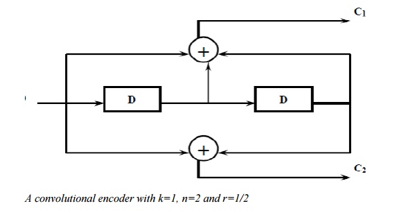
A convolutional encoder with k=1, n=2 and r=1/2
The operation of a convolutional encoder can be explained in several but equivalent ways such as, by
a) state diagram representation.
b) tree diagramrepresentation.
c) trellis diagram representation.
a) State Diagram Representation:
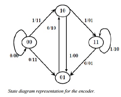
A convolutional encoder may be defined as a finite state machine. Contents of the rightmost (K-1) shift register stages define the states of the encoder. So, the encoder in Fig. 3.1 has four states.
The transition of an encoder from one state to another, as caused by input bits, is depicted in the state diagram.Fig. 3.2 shows the state diagram of the encoder in Fig. 3.1.
A new input bit causes a transition from one state to another.
b) Tree Diagram Representation:
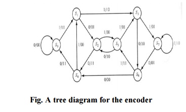
The tree diagram representation shows all possible information and encoded sequences for the convolutional encoder. Fig. 3.3 shows the tree diagram for the encoder in Fig. 3.1. The encoded bits are labeled on the branches of the tree. Given an nput sequence, the encoded sequence can be directly read from the tree. Representing convolutional codes compactly: code trellis and state diagram: State diagram
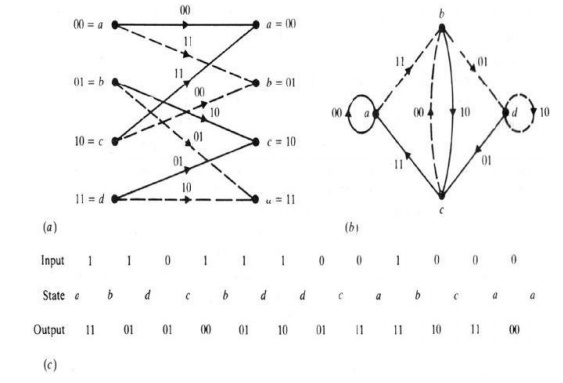
Inspecting state diagram: Structural properties of convolutional codes:
• Each new block of k input bits causes a transition into new state
• Hence there are 2k branches leaving each state
• Assuming encoder zero initial state, encoded word for any input of k bits can thus be obtained. For instance, below for u=(1 1 1 0 1), encoded wordv=(1 1, 1 0, 0 1, 0 1, 1 1, 1 0, 1 1, 1 1) is produced:
- encoder state diagram for (n,k,L)=(2,1,2) code - note that the number of states is 2L+1 = 8
Distance for some convolutional codes:
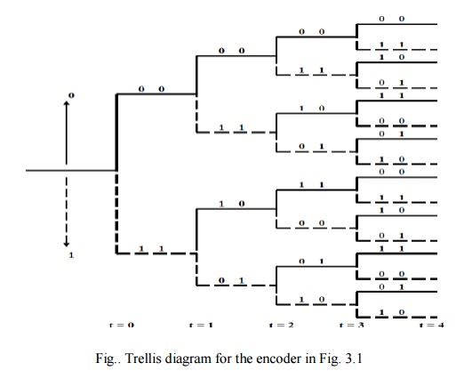
c) Trellis Diagram Representation:
The trellis diagram of a convolutional code is obtained from its state diagram. All state transitions at each time step are explicitly shown in the diagram to retain the time dimension, as is present in the corresponding tree diagram.
Usually, supporting descriptions on state transitions, corresponding input and output bits etc. are labeled in the trellis diagram.
It is interesting to note that the trellis diagram, which describes the operation of the encoder, is very convenient for describing the behavior of the corresponding decoder, especially when the famous „Viterbi‟isfollowed. Algorithm (VA)
1/3 rate convolutional encoder has the following generator g1=(1 0 0), g2=(1 0 1), g3=(1 1 1)
i)Draw the encoder circuit corresponding to this code (3)
ii) Draw the code tree (3) iii) Draw the state Diagram (3)
v) Draw the trellis Diagram (3)
v)This code is used for transmission over a Awgn channel with hard decision decoder. Using viterbi algorithm
Related Topics