Network Analysis - Construction of network | 11th Business Mathematics and Statistics(EMS) : Chapter 10 : Operations Research
Chapter: 11th Business Mathematics and Statistics(EMS) : Chapter 10 : Operations Research
Construction of network
Construction of network:
Rules for constructing network
For the construction of a
network, generally, the following rules are followed:
(i) Each
activity is represented by one and only one arrow.(i.e) only one activity can
connect any two nodes.
(ii) No
two activities can be identified by the same head and tail events.
(iii) Nodes
are numbered to identify an activity uniquely. Tail node (starting point)
should be lower than the head node (end point) of an activity.
(iv) Arrows
should not cross each other.
(v) Arrows
should be kept straight and not curved or bent.
(vi) Every node must have atleast
one activity preceding it and atleast one activity following it except for the
node at the beginning and at the end of the network.
Numbering the Events
After the network is drawn in a
logical sequence, every event is assigned a number. The number sequence must be
such as to reflect the flow of the network. In event numbering, the following
rules should be observed:
(i) Event
numbers should be unique.
(ii) Event
numbering should be carried out on a sequential basis from left to right.
(iii) The
initial event is numbered 0 or 1.
(iv) The
head of an arrow should always bear a number higher than the one assigned at
the tail of the arrow.
(v) Gap should be left in the
sequence of event numbering to accommodate subsequent inclusion of activities,
if necessary.
Remark: The above procedure of assigning
numbers to various events of a network is known as Fulkerson’s Rule.
Example 10.9
Draw the logic network for the
following:
Activities C and D both follow A
, activity E follows C , activity F follows D , activity E and F precedes B.
Solution:
The required network for the
above information.

Example 10.10
Develop a network based on the
following information:

Solution:
Using the immediate precedence
relationships and following the rules of network construction, the required
network is shown in following figure

Dummy activity:
An activity which does not
consume any resource or time, but merely depict the technological dependence is
called a dummy activity. It is represented by dotted lines.
Example 10.11
Draw a network diagram for the
project whose activities and their predecessor relationships are given below:

Solution:
Using the precedence
relationships and following the rules of network construction, the required
network diagram is shown in following figure

Example 10.12
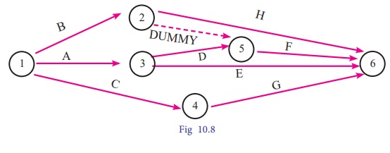
Construct a network diagram for
the following situation:
A<D,E; B,
D<F; C<G and B<H.
Solution:
Using the precedence
relationships and following the rules of network construction, the required
network is shown in following figure

Related Topics