Chapter: Mechanical : Maintenance Engineering : Condition Monitoring
Condition Monitoring
Condition Monitoring
Condition
monitoring is the process of monitoring a parameter of condition in machinery,
such that a significant change is indicative of a developing failure.
It is a
major component of predictive maintenance. The use of conditional monitoring
allows maintenance to be scheduled, or other actions to be taken to avoid the
consequences of failure, before the failure occurs.
Nevertheless,
a deviation from a reference value (e.g. temperature or vibration behavior)
must occur to identify impeding damages
Predictive Maintenance does not
predict failure.
Machines with defects are more at risk of failure than defect
free machines. Once a defect has been identified, the failure process has
already commenced and CM systems can only measure the deterioration of the
condition.
Intervention
in the early stages of deterioration is usually much more cost effective than
allowing the machinery to fail. Condition monitoring has a unique benefit in
that the actual load, and subsequent heat dissipation that represents normal
service can be seen and conditions that would shorten normal lifespan can be
addressed before repeated failures occur.
Serviceable machinery includes rotating equipment and
stationary plant such as boilers and heat exchangers.
Methods Of Cm
1.
Screen monitoring records video or static images
detailing the contents, or screen capture, of the entire [video display] or the
content of the screen activity within a particular program or computer
application. Monitoring tools may collect real time video, accelerated or
[time-lapse] video or screen shots, or may take video or still image captures
at regular intervals (e.g., once every 4 minutes). They may collect images
constantly or only collect information while the user is interacting with the
equipment (e.g., capturing screens when the mouse or keyboard is active).
2.
Data monitoring tracks the content of and changes
to files stored on the local [hard drive] or in the user's "private"
network share.
3.
Keystroke monitoring (e.g., number of keystrokes
per minute) may track the performance of keyboard-intensive work such as word
processing or data entry. Keystroke logging captures all keyboard input to
enable the employer to monitor anything typed into the monitored machine.
4.
Idle time monitoring keeps track of time when the
employee is away from the computer or the computer is not being actively used.
Benefits
o
Screen monitoring records video or static images
detailing the contents, or screen capture, of the entire [video display] or the
content of the screen activity within a particular program or computer
application.
o
Monitoring tools may collect real time video,
accelerated or [time-lapse] video or screen shots, or may take video or still
image captures at regular intervals (e.g., once every 4 minutes).
o
They may collect images constantly or only collect
information while the user is interacting with the equipment (e.g., capturing
screens when the mouse or keyboard is active).
o
Data monitoring tracks the content of and changes
to files stored on the local [hard drive] or in the user's "private"
network share.
o
Keystroke monitoring (e.g., number of keystrokes
per minute) may track the performance of keyboard-intensive work such as word
processing or data entry. Keystroke logging captures all keyboard input to
enable the employer to monitor anything typed into the monitored machine.
Idle time
monitoring keeps track of time when the employee is away from the computer or
the computer is not being actively used.
Load Testing
o
Load testing is the process of putting demand on a
system or device and measuring its response.
o
Load testing is performed to determine a system’s
behavior under both normal and anticipated peak load conditions.
o It helps to identify the maximum
operating capacity of an application as well as any bottlenecks and determine
which element is causing degradation.
o
When the load placed on the system is raised
beyond normal usage patterns, in order to test the system's response at
unusually high or peak loads, it is known as stress testing.
o
The load is usually so great that error conditions
are the expected result, although no clear boundary exists when an activity
ceases to be a load test and becomes a stress test.
o There is
little agreement on what the specific goals of load testing are. o The
term is often used
synonymously with concurrency testing, software performance testing, reliability
testing, and volume testing.
Load testing is a type of non-functional testing.
Types Of Condition Monitoring
Systems
Condition
monitoring systems are of two types: periodic and permanent. In a periodic
monitoring system (also called an off-line condition monitoring
system), machinery vibration is measured (or recorded and later
analyzed) at selected time intervals in the field; then an analysis is made
either in the field or in the laboratory.
Advanced
analysis techniques usually are required for fault diagnosis and trend analysis. Intermittent monitoring provides
information at a very early stage about incipient
failure and usually is used where (1) very early warning of faults is required,
(2) advanced diagnostics are required, (3) measurements must be made at many
locations on a machine, and (4) machines are complex.
In a permanent
monitoring system (also called an on-line condition monitoring system),
machinery vibration is measured continuously at selected points of the machine
and is constantly compared with acceptable levels of vibration.The principal function
of a permanent condition monitoring system is to protect one or more machines
by providing a warning that the machine is operating improperly and/or to shut
the machine down when a preset safety limit is exceeded, thereby avoiding catastrophic
failure and destruction. The measurement system may be permanent (as in
parallel acquisition systems where one transducer and one measurement chain are
used for each measurement point), or it may be quasi-permanent (as in multiplexed
systems where one transducer is used for each measurement point but the rest of
the measurement chain is shared between a few points with a multiplexing interval
of a few seconds).
In a
permanent monitoring system, transducers are mounted permanently at each
selected measurement point. For this reason, such a system can be very costly, so
it is usually used only in critical applications where: (1) no personnel are
available to perform measurements (offshore, remote pumping stations, etc.),
(2) it is necessary to stop the machine before a breakdown occurs in order to
avoid a catastrophic accident, (3) an instantaneous fault may occur that
requires machine shutdown, and (4) the environment (explosive, toxic, or
high-temperature) does not permit the human involvement required by
intermittent measurements.
Before a
permanent monitoring system is selected, preliminary measurements should be
made periodically over a period of time to become acquainted with the vibration
characteristics of the machine. This procedure will make it possible to select
the most appropriate vibration measurement parameter, frequency range, and normal
alarm and trip levels.
Establishing A Condition
Monitoring Program
A
condition monitoring program may be established to check the satisfactory
operation of a single machine or, more usually, it is established to check the
operation of a number of machines,
perhaps all the machines in an entire plant. The following steps are usually
considered in the establishment of such a program, depending on the type of
machine and impact of failure of operation machines might have.
Step 1. Determine
the type of condition monitoring system, described
in the preceding section, that best meets the needs of the plant.
Step 2. Make a
list of all of the machines to be monitored
(see,
for example,Table 16.1), based on the importance of these machines in
the production line.
Step 3. Tabulate
the characteristics of the machines that are
important in conducting vibration analyses of the machines of step
2.These characteristics are associated with machine construction such as the
natural frequencies of shafts, casings, and pedestals, and operational and
defect responses.A tabulation of machine frequencies is important because fault
analysis is conducted (Table 16.2) by matching machine frequencies to measured
frequencies appearing in a spectrum. The following machine characteristics
provide the necessary information for fault analysis.
_ Shaft
rotational speeds, bearing defect frequencies, number of teeth in gears, number
of vanes and blades in pumps and fans, number of motor poles, and number of stator slots and rotor bars.
Vibratory
forces such as misalignment, mass unbalance, and reciprocating masses.
_
Vibration responses due to process changes, such as temperature and pressure.
_ Fault
responses associated with specific machine types, such as motors, pumps, and fans.
_
Sensitivity to instability in components, such as fluid film bearings and seals
due to wear and clearance.
_ Loads
or changes in operating conditions.
_ Effects
of mass unbalance, misalignment, distortion, and other malfunction/defect excitations
on vibration response.
Condition Monitoring Of Machinery
TABLE
16.1 Machinery Classification for Monitoring
Machinery classification Result of failure
Critical
Unexpected shutdown or failure causes significant production loss.
Interrupts
production Unexpected shutdown or failure causes minor interruptions in
production.
Causes
inconvenience Inconvenience in operation, but no interruption in production. Noncritical
Production is not affected by failure.
Step 4. Select
the most appropriate vibration measurement
parameter. When an accelerometer is employed as the
sensing device in a condition monitoring system, the resulting acceleration
signal can be electronically integrated to obtain velocity or displacement, so any one of these three
parameters may be used in measurements.
The
appropriate parameter may be selected by application of the following simple rule:
Use the parameter which provides the “flattest”
spectrum. The flattest spectrum requires
the least dynamic range from the instrumentation which follows the transducer.
For
example,Fig. 16.1 shows a velocity spectrum and a displacement spectrum obtained
under identical conditions. The dynamic range (i.e., the range from the highest
to the lowest signal level) required to measure the displacement spectrum is much larger than the range for the velocity spectrum; it may
even exceed the available dynamic range of the instrumentation.Therefore,
according to this rule, velocity measurements should be selected.
The flattest
spectrum rule applies only to the frequency range of interest. Therefore, the
parameter selection, to some extent, depends on the type of machine and the
type of faults considered.
Step 5. Select
one of the following vibration pickups
that will best meet the requirements of step 4.
Displacement
Transducer. A displacement transducer is a
transducer that converts an input mechanical displacement into an electrical
output that is proportional to the input displacement. Displacement transducer
of the eddy-current type (described in Chap. 12), which have noncontacting
probes, are commonly used to measure the relative motion between a shaft and
its bearings. This information can be related directly to physical values such
as mechanical clearance or oil-film thickness, e.g., it can give an indication
of incipient rubbing. Shaft vibration provides information about the current
condition of a machine and is principally used in permanent monitoring systems,
which immediately shut the machine down in the event of trouble. The use of
displacement transducers is essential in machinery having journal bearings.
However, proximity probe transducers (1) usually are difficult to calibrate
absolutely, (2) have limited dynamic range because of the influence of
electrical and mechanical runout on the shaft, and (3) have a limited
high-frequency range.
Accelerometers
and Velocity Pickup. Pickups of this type, described
in Chap.
12, are
usually lightweight and rugged. They are always used for detecting faults which occur at high
frequencies (say, above 1000 Hz), for example, to detect rolling element bearing
deterioration or gearbox wear. Acceleration measurements of bearing vibration
will provide very early warning of incipient faults in a machine.
Figure
16.1 Displacement and velocity spectra obtained under
identical conditions. The velocity spectrum requires a smaller dynamic range of
the equipment which follows the transducer.Therefore, it is preferable.
Step 6. Select
the measurement locations. When a
periodic (off-line) monitoring system is employed, the number of
points at which measurements are made is limited only by the requirement for
keeping measurement time to a minimum. As a general rule, bearing vibration
measurements are made in the radial direction on each accessible bearing, and
in the axial direction on thrust bearings. It is not usually necessary to
measure bearing vibration in both the horizontal and the vertical
direction, since both measurements give the same information regarding the
forces within the machine; this information is merely transmitted through two
different transmission paths. This applies for detecting developing
faults. It will later be seen, however, that in order subsequently to diagnose
the origin of the impending fault, measurements in both the horizontal and the
vertical direction may give valuable information.When measuring shaft vibrations
with permanently mounted proximity transducers, it is convenient to use two
probes on each bearing, located at 90 from each
other, thereby providing an indication of the orbit of the shaft within the
bearing.
Axial
displacement transducers, programmed to shut the machine down on preset levels,
are mounted where a thrust measurement will protect the machine rotating parts,
such as blades, from rubbing the stationary casing due to faultinduced axial
forces.
When a
permanent (on-line) monitoring system is employed using a seismic pickup, the
number of measurement points usually is minimized for reasons of economy. Selection must be made following a
study of the vibration spectra of different bearings in order to locate those
points where all significant components related to the different expected
faults are transmitted at measurable vibration levels if full spectrum
comparison is performed. If only broadband measurements are monitored, then a
further requirement is that all frequency components related to the expected
faults must be of approximately the same level within the selected frequency
range. Otherwise, measurements must be made in selected frequency bands.
Step 7. Select
the time interval between measurements.
The
selection of the time interval between measurements requires knowledge
of the specific machine. Some machines develop faults quickly, and others run
trouble-free for years. A compromise must be found between the safety of the
system and the time taken for measurements and analysis. Measurements should be
made frequently in the initial stages of a condition monitoring program to
ensure that the vibration levels measured are stable and that no fault is
already developing.When a significant change is detected, the time interval
between measurements should be reduced sufficiently so as not to risk a
breakdown before the next measurement.The trend curve will help in determining when
the next measurement should be performed.
Step 8. Establish
an optimum sequence of data acquisition.
The
sequence in which data acquired in a condition monitoring program must
be planned so that the data are acquired efficiently. For example, the data
collection may be planned on the basis of plant layout, on the type of data
required, or on the sequence of components in the machine train, from driver to
driven components.
Principles And Methods
As a
starting point for any discussion on condition monitoring it is useful to
define what is meant by the term, and to describe how it relates to other
techniques used in the operation and maintenance of machines, such as alarm and
shut down systems or methods for failure and problem investigation.
The
crudest method for operating machines is to run them until they fail, and then
to try and repair them in order to make them fit for further service. This
method of operation can be very expensive in terms of lost output and machine
destruction, and in addition can involve hazards to personnel. It is now well
recognised that, particularly in the case of large and expensive plant, it is
more economical and operationally satisfactory to carry out regular maintenance.
This involves the maintenance of the machine or its various components at
regular intervals, to reduce the likelihood of failure during a time when the
machine is required to be available for use.
The
problem in planning this type of maintenance lies in the choice of an
appropriate maintenance interval for the machine, because the actual running time
before maintenance is really needed is not constant, but varies from one
occasion to another, due to differences in the operation of the machine in the
behaviour of its components.
Fig. 1
shows how the running time to failure of a typical machine would be likely to
vary if no preventive maintenance were carried out. The vertical line in this
diagram represents the safe time interval between preventive maintenance work
which could catch all the failures before they occurred. If this safe overhaul
interval is chosen, however, there will be many occasions when the machinery
will be overhauled long before it is really necessary,such as in those cases at
the right hand side of the curve where it could have run on for much longer
without failing.
This
situation wastes production time, and by increasing the frequency of
maintenance operations increases the incidence of human errors on reassembly of
the machine.
A more
satisfactory compromise in terms of maintenance strategy is to carry out
preventive maintenance at what may be irregular intervals, but to determine
these intervals by the actual condition of the machine at the time. For such
condition-based maintenance to be possible,it is essential to have knowledge of
the machine condition and its rate of change with time. The main function of
condition monitoring is to provide this knowledge.
There are two main methods used
for condition monitoring, and these are trend monitoring and condition checking.
Trend monitoring is the continuous or regular measurement and interpretation of
data, collected during machine operation, to indicate variations in the
condition of the machine or its components, in the interests of safe and
economical operation.
This
involves the selection of some suitable and measurable indication of machine or
component deterioration, such as one of those listed in Fig.2, and the study of
the trend in this measurement with running time to indicate when deterioration
is exceeding a critical rate.
The
principle involved is illustrated in Fig.3, which shows the way in which such
trend monitoring can give a lead time before the deterioration reaches a level
at which the machine would have to be shut down.
This lead
time is one of the main advantages of using trend monitoring rather than simple
alarms or automatic shut down devices.
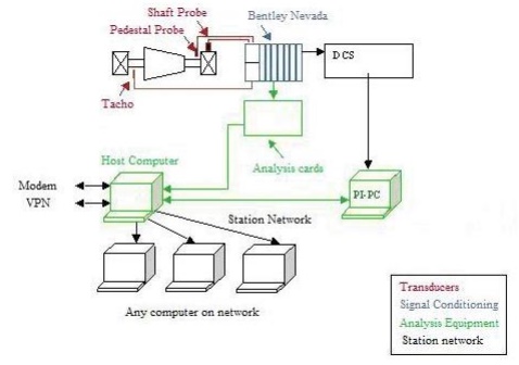
Vibration
Monitoring System (VMS) Specification
To identify potential turbine generator fault mechanisms and so
enable informed operational decisions, sophisticated vibration data analysis is
required. To do this a modern dedicated vibration monitoring system (VMS) is
required. Vibration Diagnostics can provide vibration specification and
commissioning services.
Related Topics