Chapter: Mechanical and Electrical : Thermal Engineering : Internal Combustion Engines
Components and functions of IC Engines
Components
and functions of IC Engines
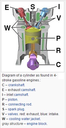
The cylinder block is the main
body of the engine, the structure that supports all the other components of the
engine. In the case of the single cylinder engine the cylinder block houses the
cylinder, while in the case of multi-cylinder engine the number of cylinders
are cast together to form the cylinder block. The cylinder head is mounted at
the top of the cylinder block. When the vehicle runs, large amounts of heat are
generated within the cylinder block. To remove this heat the cylinder block and
the cylinder head are cooled by water flowing through the water jackets within
larger engines such as those found in cars and trucks. For smaller vehicles
like motorcycles, fins are provided on the cylinder block and on the cylinder
head to cool them. The bottom portion of the cylinder block is called a
crankcase. Within the crankcase is where lubricating oil, which is used for
lubricating various moving parts of the engine, is stored.
Cylinder:
As the name suggests it is a
cylindrical shaped vessel fitted in the cylinder block. This cylinder can be
removed from the cylinder block and machined whenever required to. It is also
called a liner or sleeve. Inside the cylinder the piston moves up and down,
which is called the reciprocating motion of the piston. Burning of fuel occurs
at the top of the cylinder, due to which the reciprocating motion of the piston
is produced. The surface of the cylinder is finished to a high finish, so that
there is minimal friction between the piston and the cylinder.
Piston:
The piston is the round
cylindrical component that performs a reciprocating motion inside the cylinder.
While the cylinder itself is the female part, the piston is the male part. The
piston fits perfectly inside the cylinder. Piston rings are fitted over the
piston. The gap between the piston and the cylinder is filled by the piston
rings and lubricating oil. The piston is usually made up of aluminum
Piston rings:
The piston rings are thin rings
fitted in the slots made along the surface of the piston. It provides a tight
seal between the piston and the cylinder walls that prevents leaking of the
combustion gases from one side to the other. This ensures that that motion of
the piston produces as close as to the power generated from inside the
cylinder.
Combustion chamber:
It is in the combustion chamber
where the actual burning of fuel occurs. It is the uppermost portion of the
cylinder enclosed by the cylinder head and the piston. When the fuel is burnt,
much thermal energy is produced which generates excessively high pressures
causing the reciprocating motion of the piston.
Inlet manifold:
Through the inlet manifold the air or air-fuel mixture is
drawn into the cylinder.
Exhaust manifold:
All the exhaust gases generated
inside the cylinder after burning of fuel are discharged through the exhaust
manifold into the atmosphere.
Inlet and exhaust valves:
The inlet and the exhaust valves
are placed at the top of the cylinder in the cylinder head. The inlet valve
allows the intake of the fuel during suction stroke of the piston and to close
thereafter. During the exhaust stroke of the piston the exhaust valves open
allowing the exhaust gases to release to the atmosphere. Both these valves allow
the flow of fuel and gases in single direction only.
Spark
plug:
The spark plug is a device that produces a small
spark that causes the instant burning of the pressurized fuel.
Connecting
rod:
It is the connecting link between
the piston and the crankshaft that performs the rotary motion. There are two
ends of the connecting rod called the small end and big end. The small end of
the connecting rod is connected to the piston by gudgeon pin, while the big end
is connected to crankshaft by crank pin
Crankshaft:
The crankshaft performs the rotary motion. It is
connected to the axle of the wheels which move as the crankshaft rotates. The
reciprocating motion of the piston is converted into the rotary motion of the
crankshaft with the help of connecting rod. The crankshaft is located in the
crankcase and it rotates in the bushings.
Camshaft:
It takes driving force from crankshaft through
gear train or chain and operates the inlet valve as well as exhaust valve with
the help of cam followers, push rod and rocker arms.
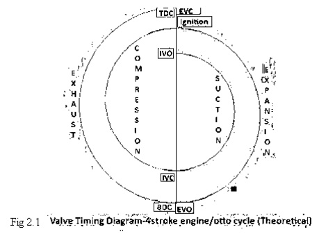
Theoretical
valve timing diagram of four stroke engine
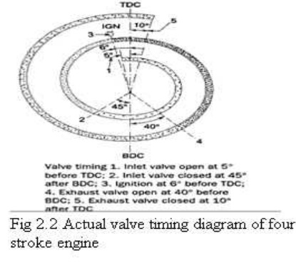
Actual valve timing
diagram of four stroke engine:
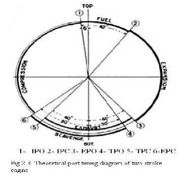
Theoretical port timing
diagram of two stroke engine:
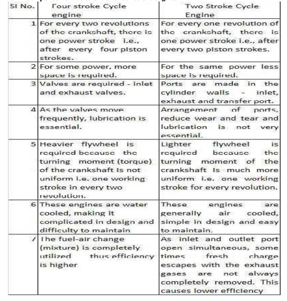
Comparison of two stroke and four
stroke engines
Related Topics