Chapter: Mechanical : Computer Aided Design : CAD Standards
CAD Standards
CAD Standards
Introduction
The purpose of CAD standard is that the
CAD software should not be device-independent and should connect to any input
device via a device driver and to any graphics display via a device drive.
The graphics system is divided into two
parts: the kernel system, which is hardware independent and the device driver,
which is hardware dependent. The kernel system, acts as a buffer independent
and portability of the program. At interface ‘X’, the application program calls
the standard functions and sub routine provided by the kernel system through
what is called language bindings. These functions and subroutine, call the
device driver functions and subroutines at interface ‘Y’to complete the task
required by the application program (Fig.5.1.).
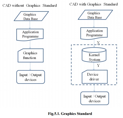
Fig.5.1.
Graphics Standard
Various standards in graphics
programming
The following international organizations involved
to develop the graphics standards:
·
ACM ( Association for Computer Machinery
)
·
ANSI ( American National Standards
Institute )
·
ISO ( International Standards
Organization )
·
GIN ( German Standards Institute )
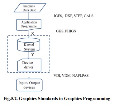
Fig.5.2.
Graphics Standards in Graphics Programming
As a result of these
international organization efforts, various standard functions at various
levels of the graphics system developed. These are:
1. IGES
(Initial Graphics Exchange Specification) enables an exchange of model data
basis among CAD system.
2. DXF
(Drawing / Data Exchange Format) file format was meant to provide an exact
representation of the data in the standard CAD file format.
3. 3. STEP
(Standard for the
Exchange of Product model
data) can be used to exchange
data between CAD, Computer Aided
Manufacturing (CAM) ,
Computer Aided Engineering (CAE) , product data management/enterprise data
modeling (PDES) and other CAx systems.
4. CALS
( Computer Aided Acquisition and Logistic Support) is an US Department of
Defense initiative with the aim of applying computer technology in Logistic
support.
5. GKS
(Graphics Kernel System) provides a set of drawing features for two-dimensional
vector graphics suitable for charting and similar duties.
6. PHIGS
( Programmer’sHierarchical Interactive Graphic System) The PHIGS standard
defines a set of functions and data structures to be used by a programmer to
manipulate and display 3-D graphical objects.
7. VDI
(Virtual Device Interface) lies between GKS or PHIGS and the device driver code.
VDI is now called CGI (Computer Graphics Interface).
8. VDM
(Virtual Device Metafile) can be stored or transmitted from graphics device to
another. VDM is now called CGM (Computer Graphics Metafile).
9. NAPLPS
(North American Presentation- Level Protocol Syntax) describes text and
graphics in the form of sequences of bytes in ASCII code.
Graphics Kernel System
(GKS)
The Graphical Kernel
System (GKS) was the first ISO standard for computer graphics in low-level,
established in 1977. GKS offers a group of drawing aspects for 2D vector
graphics appropriate for mapping and related duties. The calls are defined to
be moveable across various programming languages, graphics hardware, so that
applications noted to use GKS will be willingly portable to different devices
and platforms.
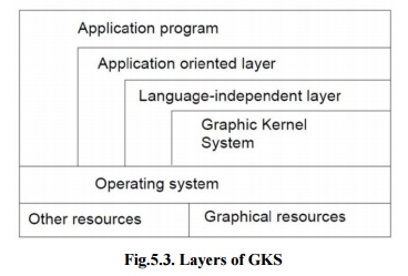
Fig.5.3.
Layers of GKS
The
following documents are representing GKS standards:
· The
language bindings are called in ISO 8651 standard.
· ANSI
X3.124 (1985) is part of ANSI standard.
· ISO/IEC
7942 noted in ISO standard, first part of 1985 and two to four parts of
1997-99.
· ISO
8805 and ISO 8806.
The main uses of the GKS standard are:
·
To give for portability of application
graphics programs.
·
To assist in the learning of graphics
systems by application programmers.
·
To offer strategy for manufacturers in
relating practical graphics capabilities.
The GKS consists of three basic parts:
i) A
casual exhibition of the substances of the standard which contains such things
as how text is placed, how polygonal zones are to be filled, and so onward.
ii) An
official of the descriptive material in (i), by way of conceptual the
ideas into separate functional explanations. These functional descriptions have
such data as descriptions of input and output parameters, specific descriptions
of the result of every function should have references into the descriptive
material in (i), and a description of fault situation. The functional
descriptions in this division are language autonomous.
iii) Language
bindings are an execution of the abstract functions explained in (ii). in a
explicit computer language such as C.
GKS arrange its
functionality into twelve functional stages, based on the complexity of the
graphical input and output. There are four stages of output (m, 0, 1, 2) and
three stages of input (A, B, C). NCAR GKS has a complete execution of the GKS C
bindings at level 0 A.
1. GKS Output Primitives
GKS is based on a
number of elements that may be drawn in an object know as graphical primitives.
The fundamental set of primitives has the word names POLYLINE, POLYMARKER,
FILLAREA, TEXT and CELLARRAY, even though a few implementations widen this
basic set.
i) POLYLINES
The GKS
function for drawing
line segments is
called ‘POLYLINE’The. ‘POLYLINE’
command takes an array
of X-Y coordinates and creates line segments joining them. The elements that
organize the look of a ‘POLYLINE’re (Figa.5.3):
• Line type : solid, dashed or
dotted.
• Line width scale factor : thickness
of the line.
·
Polyline color index : color of the line.
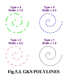
Fig.5.3.
GKS POLYLINES
ii) POLYMARKERS
The GKS
OLYMARKER‘P’function permits to draw symbols of marker centered at coordinate
points. The features that control the look of ‘POLYMARKERS’are (Fig.5.4.):
·
Marker characters : dot,
plus, asterisk, circle or cross.
·
Marker size scale factor : size of
marker
·
Polymarker color index : color of
the marker.
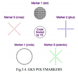
Fig.5.4.
GKS POLYMARKERS
iii) FILLAREA
The GKS
ILL‘FAREA’function permits to denote a polygonal shape of a zone to be filled
with various interior shapes. The features that control the look of fill areas
are (Fig.5.5.):
· FILL AREA interior style : solid colors, hatch patterns.
· FILL AREA style index :
horizontal lines; vertical lines; left slant lines;
right
slant lines; horizontal and vertical lines; or left slant
and
right slant lines.
· Fill area color index :
color of the fill patterns / solid areas.
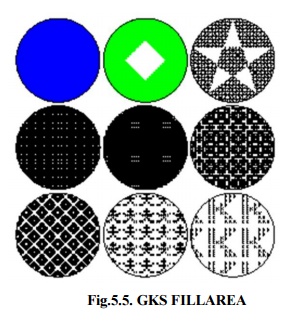
Fig.5.5.
GKS FILLAREA
iv) TEXT
The GKS TEXT function
permits to sketch a text string at a specified coordinate place. The features
that control the look of text are:
·
Text font and precision : text
font should be used for the characters
·
Character expansion factor :
height-to-width ratio of each character.
·
Character spacing :
additional white space should be inserted between characters
·
Text color index :
color the text string
·
Character height : size
of the characters
·
Character up vector : angle
the text
·
Text path :
direction the text should be written (right, left, up, or down).
· Text alignment : vertical and horizontal centering options for the text string.
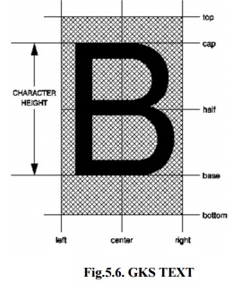
Fig.5.6.
GKS TEXT
v) CELL ARRAY
The GKS CELL ARRAY
function shows raster like pictures in a device autonomous manner. The CELL
ARRAY function takes the two corner points of a rectangle that indicate, a
number of partitions (M) in the X direction and a number of partitions (N) in
the Y direction. It then partitions the rectangle into M x N sub rectangles
noted as cells.
Fig.5.7. GKS CELL ARRAY
Standard for exchange images
A graphics standard
proposed for interactive Three Dimensional applications should assure different
criteria. It should be introduced on platforms with changing graphics abilities
without sacrificing the graphics quality of the primary hardware and without
compromising control over the hardware’s function. It must offer a normal
interface that permits a programmer to explain rendering processes quickly.
To end with, the
interface should be flexible adequate to contain additions, hence that as new
graphics operations become important, these operations can be given without
sacrificing the original interface. OpenGL meets these measures by giving a
simple interface to the basic operations of 3D graphics rendering. It supports
basic graphics primitives, basic rendering operations and lighting
calculations. It also helps advanced rendering attributes such as texture
mapping.
1. Open Graphics Library
OpenGL draws primitives
into a structured buffer focus to a various selectable modes. Every Point,
line, polygon, or bitmap are called as a primitive. Each mode can be modified
separately; the parameters of one do not affect the parameters of others. Modes
defined, primitives detailed, and other OpenGL operations explained by giving
commands in the form of procedure calls.
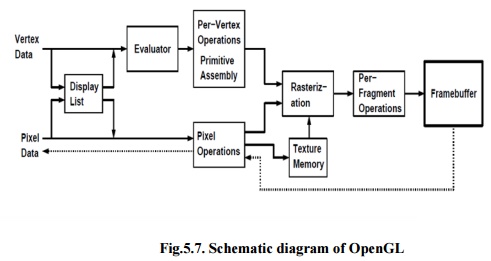
Fig.5.7.
Schematic diagram of OpenGL
Figure 5.7 shows a
schematic diagram of OpenGL. Commands go into OpenGL on the left. The majority
commands may be collected in a ‘display list’for executing at a later time. If
not, commands are successfully sent through a pipeline for processing.
The first stage gives
an effective means for resembling curve and surface geometry by estimating
polynomial functions of input data. The next stage works on geometric
primitives explained by vertices. In this stage vertices are converted, and
primitives are clipped to a seeing volume in creation for the next stage.
All ‘fragment’created
is supplied to the next stage that executes processes on personal fragments
before they lastly change the structural buffer. These operations contain
restricted updates into the structural buffer based on incoming and formerly
saved depth values, combination of incoming colors with stored colors, as well
as covering and other logical operations on fragment values.
To end with, rectangle
pixels and bitmaps by pass the vertex processing part of the pipeline to move a
group of fragments in a straight line to the individual fragment actions,
finally rooting a block of pixels to be written to the frame buffer. Values can
also be read back from the frame buffer or duplicated from one part of the
frame buffer to another. These transfers may contain several type of encoding
or decoding.
2. Features of OpenGL
i) Based on IRIS GL
OpenGL is supported on
Silicon Graphics’Integrated Rater Imaging System Graphics Library (IRIS GL).
Though it would have been potential to have designed a totally new Application
Programmer’sInterface (API), practice with IRIS GL offered insight into what
programmers need and don’tneed in a Three Dimensional graphics API. Additional,
creation of OpenGL similar to Integrated Rater Imaging System Graphics Library
where feasible builds OpenGL most likely to be admitted; there are various
successful IRIS GL applications, and programmers of IRIS GL will have a simple
time switching to OpenGL.
ii) Low-Level
A critical target of
OpenGL is to offer device independence while still permitting total contact to
hardware. Therefore the API gives permission to graphics operations at the
lowest level that still gives device independence. Hence, OpenGL does not give
a suggestion for modeling complex geometric objects.
iii) Fine-Grained Control
Due to minimize the
needs on how an application utilizing the Application Programmer’s Interface
must save and present its information, the API must give a suggestion to state
entity parts of geometric entities and operations on them. This fine-grained
control is necessary so that these mechanism and operations may be defined in
any order and so that control of rendering operations is comfortable to contain
the needs of various applications.
iv) Modal
A modal Application
Programmer’sInterface arises in executions in which processes function in
parallel on different primitives. In that cases, a mode modify must be transmit
to all processors so that all collects the new parameters before it processes
its next primitive. A mode change is thus developed serially, stopping
primitive processing until all processors have collected the modifications, and
decreasing performance accordingly.
v) Frame buffer
Most of OpenGL needs
that the graphics hardware has a frame buffer. This is a realistic condition
since almost all interactive graphics run on systems with frame buffers. Some
actions in OpenGL are attained only during exposing their execution using a
frame buffer. While OpenGL may be applied to give data for driving such devices
as vector displays, such use is minor.
vi) Not Programmable
OpenGL does not give a
programming language. Its function may be organized by turning actions on or
off or specifying factors to operations, but the rendering algorithms are
basically fixed. One basis for this decision is that, for performance basis,
graphics hardware is generally designed to apply particular operations in a
defined order; changing these operations with random algorithms is generally
infeasible. Programmability would variance with maintenance of the API close to
the hardware and thus with the objective of maximum performance.
vii) Geometry and Images
OpenGL gives support
for managing both 3D and 2D geometry. An Application Programmer’s Interface for
utilize with geometry should also give guidance for reading, writing, and
copying images, because geometry and images are regularly joint, as when a
Three Dimensional view is laid over a background image. Various per-fragment
processes that are applied to fragments beginning from geometric primitives
apply uniformly well to fragments corresponding to pixels in an image, making
it simple to mix images with geometry.
Related Topics