Chapter: Mechanical : Computer Aided Design : CAD Standards
Graphics Kernel System (GKS)
Graphics Kernel System (GKS)
The Graphical Kernel System (GKS) was the first ISO standard for computer graphics in low-level, established in 1977. GKS offers a group of drawing aspects for 2D vector graphics appropriate for mapping and related duties. The calls are defined to be moveable across various programming languages, graphics hardware, so that applications noted to use GKS will be willingly portable to different devices and platforms.
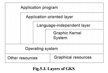
Fig.5.3. Layers of GKS
The following documents are representing GKS standards:
· The language bindings are called in ISO 8651 standard.
· ANSI X3.124 (1985) is part of ANSI standard.
· ISO/IEC 7942 noted in ISO standard, first part of 1985 and two to four parts of 1997-99.
· ISO 8805 and ISO 8806.
The main uses of the GKS standard are:
· To give for portability of application graphics programs.
· To assist in the learning of graphics systems by application programmers.
· To offer strategy for manufacturers in relating practical graphics capabilities.
The GKS consists of three basic parts:
i) A casual exhibition of the substances of the standard which contains such things as how text is placed, how polygonal zones are to be filled, and so onward.
ii) An official of the descriptive material in (i), by way of conceptual the ideas into separate functional explanations. These functional descriptions have such data as descriptions of input and output parameters, specific descriptions of the result of every function should have references into the descriptive material in (i), and a description of fault situation. The functional descriptions in this division are language autonomous.
iii) Language bindings are an execution of the abstract functions explained in (ii). in a explicit computer language such as C.
GKS arrange its functionality into twelve functional stages, based on the complexity of the graphical input and output. There are four stages of output (m, 0, 1, 2) and three stages of input (A, B, C). NCAR GKS has a complete execution of the GKS C bindings at level 0 A.
1. GKS Output Primitives
GKS is based on a number of elements that may be drawn in an object know as graphical primitives. The fundamental set of primitives has the word names POLYLINE, POLYMARKER, FILLAREA, TEXT and CELLARRAY, even though a few implementations widen this basic set.
i) POLYLINES
The GKS function for drawing line segments is called ‘POLYLINE’The. ‘POLYLINE’
command takes an array of X-Y coordinates and creates line segments joining them. The elements that organize the look of a ‘POLYLINE’re (Figa.5.3):
• Line type : solid, dashed or dotted.
• Line width scale factor : thickness of the line.
· Polyline color index : color of the line.
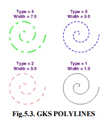
Fig.5.3. GKS POLYLINES
ii) POLYMARKERS
The GKS OLYMARKER‘P’function permits to draw symbols of marker centered at coordinate points. The features that control the look of ‘POLYMARKERS’are (Fig.5.4.):
· Marker characters : dot, plus, asterisk, circle or cross.
· Marker size scale factor : size of marker
· Polymarker color index : color of the marker.
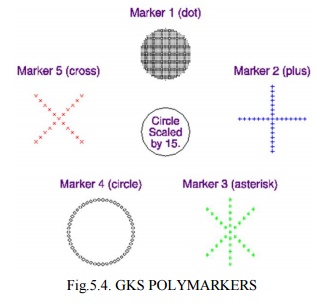
Fig.5.4. GKS POLYMARKERS
iii) FILLAREA
The GKS ILL‘FAREA’function permits to denote a polygonal shape of a zone to be filled with various interior shapes. The features that control the look of fill areas are (Fig.5.5.):
· FILL AREA interior style : solid colors, hatch patterns.
· FILL AREA style index : horizontal lines; vertical lines; left slant lines;
right slant lines; horizontal and vertical lines; or left slant
and right slant lines.
· Fill area color index : color of the fill patterns / solid areas.
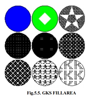
Fig.5.5. GKS FILLAREA
iv) TEXT
The GKS TEXT function permits to sketch a text string at a specified coordinate place. The features that control the look of text are:
· Text font and precision : text font should be used for the characters
· Character expansion factor : height-to-width ratio of each character.
· Character spacing : additional white space should be inserted between characters
· Text color index : color the text string
· Character height : size of the characters
· Character up vector : angle the text
· Text path : direction the text should be written (right, left, up, or down).
· Text alignment : vertical and horizontal centering options for the text string.
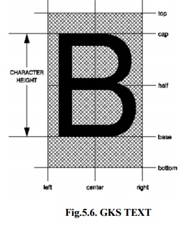
Fig.5.6. GKS TEXT
v) CELL ARRAY
The GKS CELL ARRAY function shows raster like pictures in a device autonomous manner. The CELL ARRAY function takes the two corner points of a rectangle that indicate, a number of partitions (M) in the X direction and a number of partitions (N) in the Y direction. It then partitions the rectangle into M x N sub rectangles noted as cells.
Fig.5.7. GKS CELL ARRAY
Related Topics