Chapter: civil : Applied Hydraulic Engineering: Uniform Flow
Applied Hydraulic Engineering: Uniform Flow - Fundamental equations

Fundamental equations
The
equations which describe the flow of fluid are derived from three fundamental
laws of physics:
1. Conservation of matter (or mass)
2. Conservation of energy
3. Conservation of
momentum
Although
first developed for solid bodies they are equally applicable to fluids. Brief
descriptions of the concepts are given below.
Conservation
of matter
This says
that matter can
not be created nor destroyed,
but it may
be converted (e.g. by a chemical
process.) In fluid mechanics we do not consider chemical activity so the law
reduces to one of conservation of mass.
Conservation of energy
This says that energy
can not be created nor destroyed, but may be converted form one type to another
(e.g. potential may be converted to kinetic energy). When engineers talk about
energy "losses" they are referring to energy converted from
mechanical (potential or kinetic) to some other form such as heat. A friction
loss, for example, is a conversion of mechanical energy to heat. The basic
equations can be obtained from the First Law of Thermodynamics but a simplified
derivation will be given below.
Conservation of momentum
The law of conservation
of momentum says that a moving body cannot gain or lose momentum unless acted
upon by an external force. This is a statement of Newton's Second Law of
Motion: Force = rate of change of momentum
In solid mechanics
these laws may be applied to an object which is has a fixed shape and is
clearly defined. In fluid mechanics the object is not clearly defined and as it
may change shape constantly. To get over this we use the idea of control
volumes. These are imaginary volumes of fluid within the body of the fluid. To
derive the basic equation the above conservation laws are applied by
considering the forces applied to the edges of a control volume within the
fluid.
The Continuity Equation (conservation of
mass)
For any control volume
during the small time interval ?t the principle of conservation of mass
implies that the mass of flow entering the control volume minus the mass of
flow leaving the control volume equals the change of mass within the control
volume.If the flow is steady and the fluid incompressible the mass entering is
equal to the mass leaving, so there is no change of mass within the control
volume.
So
for the time interval ?t : Mass flow entering = mass flow leaving
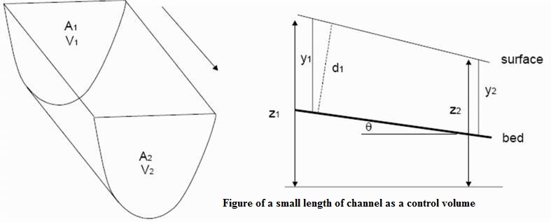
Considering
the control volume above which is a short length of open channel of arbitrary
cross- Section then, if ? is the fluid density and Q is the volume flow
rate then section then, if mass flow rate is ? Q and the continuity
equation for steady incompressible flow can be written
pQentering
= pQleaving
As,
Q, the volume flow rate is the product of the area and the mean velocity
then at the upstream face (face 1) where the mean velocity is u and the
cross-sectional area is A1 then:
Qentering
= u1A1
Similarly
at the downstream face, face 2, where mean velocity is u2 and the
cross-sectional area is A2 then:
Qleaving=
u2A2
Therefore
the continuity equation can be written as
u1A1
= u2A2
The
Energy equation (conservation of energy):
Consider the forms of energy
available for the above control volume. If the fluid moves from the upstream
face 1, to the downstream face 2 in time d t over the length L.
The work
done in moving the fluid through face 1 during this time is
Where p1 is pressure at face 1
Work
done = p1A1L
The mass entering through face 1 is
Mass
entering = p1A1L
Therefore
the kinetic energy of the system is:
KE
= � mu2 = � p1A1Lu12
If z1
is the height of the centroid of face 1, then the potential energy of the fluid
entering the control volume is :
PE
= mgz = p1A1Lgz1
The total
energy entering the control volume is the sum of the work done, the potential
and the kinetic energy:
Total
energy = p1A1L + � p1A1Lu12
+ p1A1Lgz1
We can
write this in terms of energy per unit weight. As the weight of water entering
the control volume is ?1 A1 L g then just
divide by this to get the total energy per unit weight:
Total
energy per unit weight = p1/p1g + u12 + z1
At the
exit to the control volume, face 2, similar considerations deduce
Total
energy per unit weight = p2/p2g + u22 + z2
If no
energy is supplied to the control volume from between the inlet and the outlet
then energy leaving = energy entering and if the in compressible
p1/p1g +
u12 + z1 + p2/p2g + u22 + z2
= H = constant
This is
the Bernoulli equation.
Note:
1. In the
derivation of the Bernoulli equation it was assumed that no energy is lost in
the control volume - i.e. the fluid is frictionless. To apply to non
frictionless situations some energy loss term must be included.
The
dimensions of each term in equation 1.2 has the dimensions of length ( units of
meters). For this reason each term is often regarded as a "head" and
given the names
P/pg=pressure
head
U2/2g
= velocity head
Z=velocity
or potential head
3. Although above we derived the Bernoulli equation between
two sections it should strictly speaking be applied along a stream line as the
velocity will differ from the top to the bottom of the section. However in
engineering practise it is possible to apply the Bernoulli equation with out
reference to the particular streamline
The
momentum equation (momentum principle)
Again
consider the control volume above during the time ?t
Momentum entering = p ?Q1?tu1
Momentum entering = p ?Q2?tu2
By the
continuity principle : = d Q1 = dQ
2 = dQ
And by
Newton's second law Force = rate of change of momentum
It is
more convenient to write the force on a control volume in each of the three, x,
y and z direction e.g. in the x-direction
Integration
over a volume gives the total force in the x-direction as
Fx = pQ(V2x
- V1x)
As long
as velocity V is uniform over the whole
cross-section.
This is
the momentum equation for steady flow for a region of uniform velocity.
Energy and Momentum coefficients
In deriving the above momentum and energy
(Bernoulli) equations it was noted that the velocity must be constant (equal to
V) over the whole cross-section or constant along a stream-line.
Clearly
this will not occur in practice. Fortunately both these equation may still be
used even for situations of quite non-uniform velocity distribution over a
section. This is possible by the introduction of coefficients of energy and
momentum, a and � respectively.
where V
is the mean velocity.
And the
Bernoulli equation can be rewritten in terms of this mean velocity:
P/pg + aV2/2g
+ z = constant
And the momentum equation becomes:
Fx = pQB(V2x
- V1x)
The values of ? and �
must be derived from the velocity distributions across a cross-section. They
will always be greater than 1, but only by a small amount consequently they can
often be confidently omitted - but not always and their
existence should always be remembered.
For
turbulent flow in regular channel a does not usually go above 1.15 and � will
normally be below 1.05. We will see an example below where their inclusion is
necessary to obtain accurate results.
Related Topics