Chapter: Cryptography and Network Security Principles and Practice : One Symmetric Ciphers : Advanced Encryption Standard
Advanced Encryption Standard(AES) Transformation Functions
AES TRANSFORMATION FUNCTIONS
We now turn to a discussion of each of the four
transformations used in AES. For each
stage, we describe
the forward (encryption) algorithm, the inverse
(decryption) algorithm, and the rationale for the stage.
Substitute Bytes
Transformation
FORWARD AND INVERSE TRANSFORMATIONS The forward substitute byte transformation, called SubBytes, is a
simple table lookup (Figure 5.5a). AES
defines a 16 * 16 matrix of byte values, called an S-box (Table
5.2a), that contains a permutation of all possible 256 8-bit values. Each
individual byte of State is mapped into a
new byte in the following way: The leftmost 4 bits of the byte are
used as a row value and the rightmost 4
bits are used as a column value.
These row and column values
serve as indexes
into the S-box
to select a unique 8-bit output value. For example, the hexadecimal value3 {95} references row 9, column
5
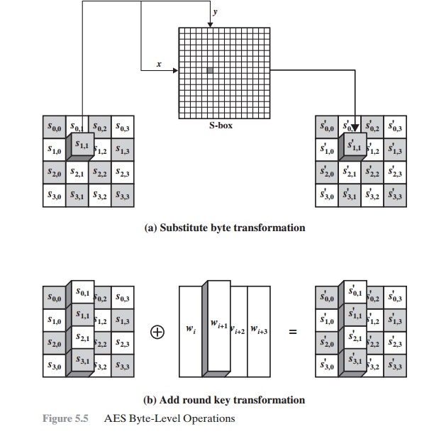
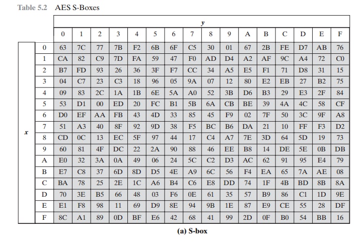
of the S-box, which contains the value {2A}.
Accordingly, the value {95} is mapped into the value {2A}.
Here is an example of the SubBytes transformation:
The S-box is constructed in the following fashion (Figure 5.6a).
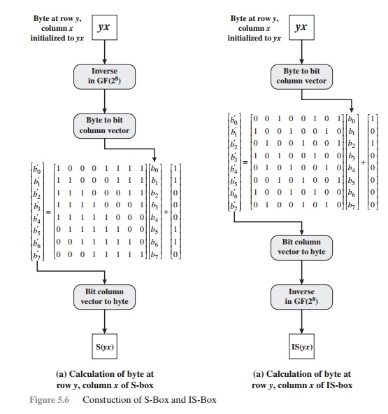
1.
Initialize the S-box
with the byte values in ascending sequence row by row.
The first row
contains {00}, {01}, {02}, ... , {0F}; the second
row
contains
{10}, {11}, etc.;
and so on. Thus, the value
of the byte at row y, column x is {yx}.
2.
Map each byte in the S-box to its multiplicative
inverse in the finite field GF(28); the value {00} is mapped
to itself.
3.
Consider that each byte in the S-box consists
of 8 bits labeled (b7, b6, b5, b4, b3, b2, b1, b0). Apply
the following transformation to each bit of each byte in the
S-box:

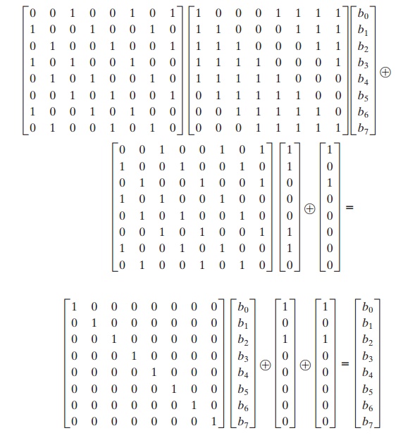
where ci is the ith bit of byte c with the value {63}; that is,
(c7c6c5c4c3c2c1c0) = (01100011). The prime (¿) indicates that the variable is to be updated by the value on the right. The AES standard
depicts this transformation in matrix
form as follows.
Equation (5.2) has to be interpreted
carefully. In ordinary matrix multiplica- tion,4 each element in the product matrix is the sum of products
of the elements of one row and one
column. In this case, each element in the product matrix is the bitwise
XOR of products of elements
of one row and one column. Furthermore, the final addition shown in Equation (5.2) is a bitwise XOR.
Recall from Section 4.7 that the bitwise
XOR is addition in GF(28).
As an example, consider the input value
{95}. The multiplicative inverse in GF(28) is {95} - 1 = {8A},
which is 10001010 in binary. Using Equation (5.2),
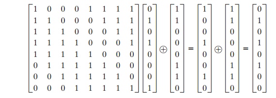
The result is {2A}, which should appear in
row {09} column {05} of the S-box.
This is verified by checking Table 5.2a.
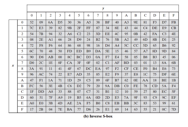
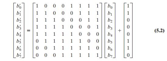
The inverse
substitute byte transformation, called InvSubBytes, makes use of
the inverse S-box shown in Table 5.2b. Note, for example, that the input
{2A} produces the output
{95}, and the input {95} to the S-box produces
{2A}. The inverse S-box is constructed
(Figure 5.6b) by applying the inverse of the transfor- mation in Equation (5.1) followed by taking the multiplicative inverse in GF(28).
The inverse transformation is
bi¿ = b(i + 2) mod
8 Ⓧ b(i + 5) mod
8 Ⓧ b(i + 7)
mod 8 Ⓧ di
where byte d = {05},
or 00000101. We can depict this transformation as follows.
To see that InvSubBytes is the inverse of
SubBytes, label the matrices in SubBytes and InvSubBytes as X and B, respectively,
and the vector versions of con- stants c and d as C and D, respectively. For
some 8-bit vector B,
Equation (5.2) becomes B¿ = XB Ⓧ C. We need to show
that Y(XB Ⓧ C) Ⓧ
D =
B. To multiply out, we must show
YXB Ⓧ YC Ⓧ D = B. This
becomes
We have demonstrated that YX equals the
identity matrix, and the YC = D, so that YC Ⓧ D equals the null vector.
RATIONALE The
S-box is designed to be resistant to
known cryptanalytic attacks. Specifically,
the Rijndael developers sought a design that has a low correlation between input bits and output
bits and the property that the output is not a linear mathematical function of
the input [DAEM01]. The nonlinearity is due to the use of the multiplicative
inverse. In addition,
the constant in Equation (5.1)
was chosen so that the S-box has no fixed points [S-box(a) = a] and no “opposite fixed
points” [S-box(a) = Bar a], where Bar a is the bitwise
complement of a.
Of course,
the S-box must
be invertible, that is, IS-box[S-box(a)] =
a.
However, the
S-box does not
self-inverse in the
sense that it
is not true that S-box(a) = IS-box(a). For example, S-box({95}) =
{2A}, but IS-box({95}) = {AD}.
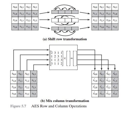
ShiftRows Transformation
FORWARD AND INVERSE TRANSFORMATIONS
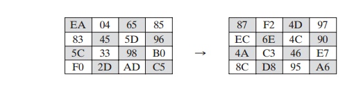
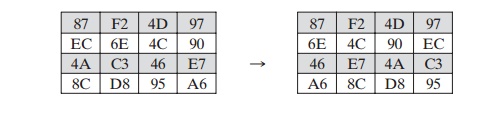
The forward shift row transformation, called ShiftRows, is depicted in
Figure 5.7a. The first row of State is
not altered. For the second row, a 1-byte circular left shift is performed. For
the third row, a 2-byte circular left shift is performed. For the fourth row, a
3-byte circular left shift is performed. The following is an example of
ShiftRows.
The inverse shift row transformation, called
InvShiftRows, performs the circu-
lar shifts in the opposite direction for each of the last three rows, with a 1-byte circular right shift for the second row, and so on.
RATIONALE
The shift row transformation is more
substantial than it may first appear. This is because the State, as well as the cipher input and output, is treated as an
array of four 4-byte columns. Thus, on encryption, the first 4 bytes of the
plaintext are copied to the first column of State, and so on. Furthermore, as will be seen, the round key is
applied to State column by column.
Thus, a row shift moves an individual byte from one column to another, which is
a linear
distance of a multiple of 4 bytes. Also note that the transformation
ensures that the 4 bytes of one column are spread out to four different
columns. Figure 5.4 illustrates the
effect.
MixColumns Transformation
FORWARD AND INVERSE TRANSFORMATIONS The forward mix column transformation, called
MixColumns, operates on each column individually. Each byte of a column is
mapped into a new value that is a function of all four bytes in that column.
The transformation can be defined
by the following matrix multiplication on State (Figure 5.7b):
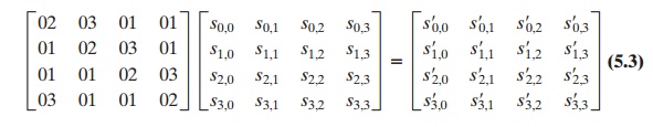
Each element
in the product matrix is the sum of products
of elements of one row and one
column. In this case,
the individual additions and multiplications5 are performed in GF(28). The MixColumns transformation on a single
column of State can be expressed as
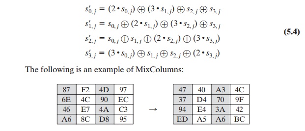
Let us verify the first column of this example. Recall from Section
4.7 that, in GF(28), addition is the bitwise XOR
operation and that multiplication can be per- formed according to the rule established in Equation (4.14).
In particular, multipli- cation of a value
by x (i.e., by {02}) can be implemented as a 1-bit
left shift followed by a conditional bitwise XOR
with (0001 1011) if the leftmost bit of the original value (prior
to the shift) is 1. Thus, to verify
the MixColumns transformation on the first column,
we need to show that
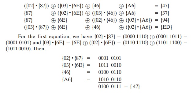
The other equations can be similarly verified.
The inverse mix column transformation, called
InvMixColumns, is defined by the following matrix multiplication:
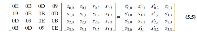
It is not immediately clear
that Equation (5.5)
is the inverse of
Equation (5.3).
We
need to show
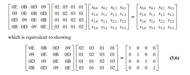
That
is, the inverse transformation matrix times the forward transformation matrix
equals the identity matrix. To verify the first column of Equation (5.6), we
need to show
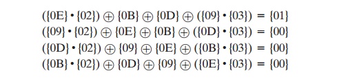
For the
first equation, we have
{0E} . {02} = 00011100
and {09} . {03} = {09} Ⓧ ({09}
# {02}) = 00001001 Ⓧ 00010010 = 00011011.
Then
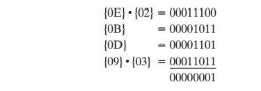
The other equations can be similarly verified.
The AES document describes another way of characterizing the MixColumns
transformation, which is in terms
of polynomial arithmetic. In the standard,
MixColumns is defined
by considering each column of State to be a four-term poly- nomial with coefficients in GF(28). Each column is multiplied
modulo (x4 + 1) by the fixed polynomial a(x),
given by
a(x) = {03}x3 + {01}x2 + {01}x + {02} (5.7)
Appendix
5A demonstrates that multiplication of each column of State by a(x) can be written as the matrix
multiplication of Equation (5.3). Similarly, it can be seen that the
transformation in Equation (5.5) corresponds to treating each column as a four-term polynomial and
multiplying each column by b(x), given by
b(x) = {0B}x3 + {0D}x2 + {09}x + {0E} (5.8)
It readily
can be shown that b(x) = a - 1(x) mod (x4 + 1).
RATIONALE The coefficients
of the matrix in Equation (5.3) are based on a linear code with maximal distance between code words, which ensures a good mixing among the bytes of each column.
The mix column transformation combined with the shift row transformation ensures that
after a few rounds all output bits depend on all input bits.
See [DAEM99] for a discussion.
In
addition, the choice of coefficients in MixColumns, which are all {01}, {
02}, or { 03}, was influenced by
implementation considerations. As was discussed, multi- plication by these
coefficients involves at most a shift and an XOR. The coefficients in InvMixColumns are more formidable to
implement. However, encryption was deemed
more important than
decryption for two reasons:
1.
For the CFB and OFB cipher modes (Figures 6.5 and 6.6; described in Chapter
6), only encryption
is used.
2.
As with any block cipher,
AES can be used to construct a message authentica- tion code (Chapter 12), and for this, only encryption is used.
AddRoundKey
Transformation
FORWARD AND INVERSE TRANSFORMATIONS In the forward
add round key transfor- mation, called AddRoundKey, the 128 bits of State are bitwise XORed with the 128 bits of the round key. As shown in Figure 5.5b, the
operation is viewed as a columnwise operation between the 4 bytes of a State column and one word of the round key; it can also be viewed as a byte-level operation. The following
is an example of AddRoundKey:
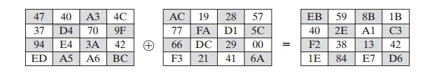
The first matrix is State, and
the second matrix is the round key.
The inverse
add round key transformation is identical to the forward add round key
transformation, because the XOR operation is its own inverse.
RATIONALE
The add round key
transformation is as simple as possible and affects every bit of State. The complexity of the round
key expansion, plus the complexity of the other stages of AES, ensure security.
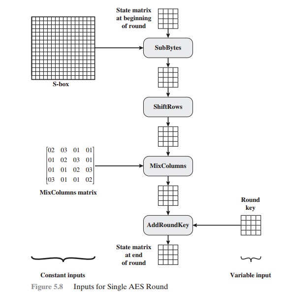
Figure
5.8 is another view of a single round of AES, emphasizing the mecha- nisms and
inputs of each transformation.
Related Topics