Chapter: Electronic Circuits : BJT Amplifiers
A.C. Analysis of Differential Amplifier using h-Parameters
A.C. Analysis of Differential
Amplifier using h-Parameters
In the
a.c. analysis, we will calculate the differential gain Ad, common
mode gain A C, input resistance Ri and the output resistance R 0
of the differential amplifier circuit, using the h-parameters.
1. Differential Gain (A d)
For the
differential gain calculation, the two input signals must be different from
each other. Let the two a.c. input signals be equal in magnitude but having
180" phase difference in between them. The magnitude of each a.c. input
voltage V S1 and V S2beVs /2. The two a.c. emitter
currents I e1 and I e2 are equal in magnitude and 180'
out of phase. Hence they cancel each other to get resultant a.c. current
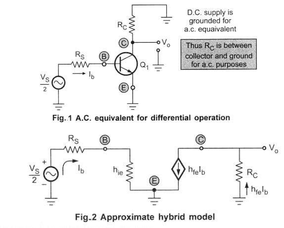
through the emitter as zero. For the a.c. purposes emitter terminal can be
grounded. The a.c. small signal differential amplifier circuit with grounded
emitter terminal is shown in the Fig1 As the two transistors are matched, the
a.c. equivalent circuit for the other transistor is identical to the one shown
in the Fig..1. Thus the circuit can be analyzed by considering only one
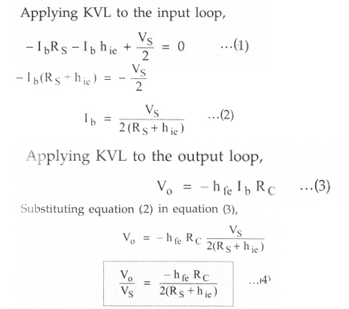
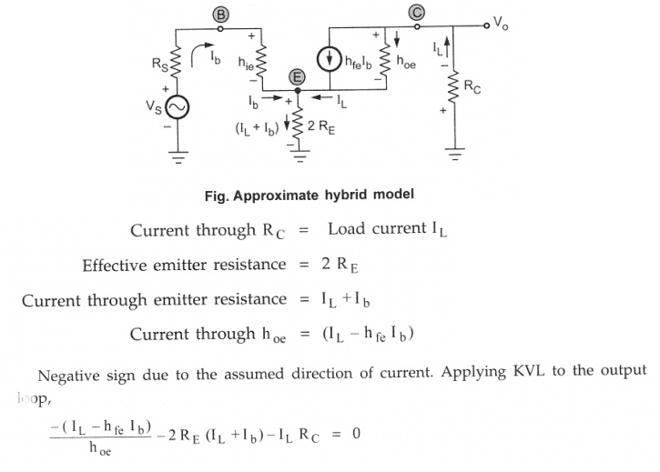
transistor. This is called as half circuit concept of analysis. The approximate
hybrid model for the above circuit can be shown as in the Fig.2, neglecting hoe,
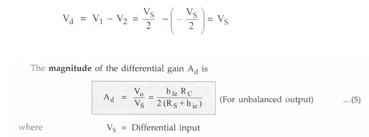
The
negative sign indicates the phase difference between input and output. Now two
input signal magnitudes are VS /2 but they are opposite in polarity,
as 180" out of phase.
the
expression for A d with balanced output changes as
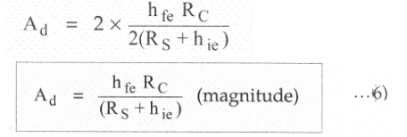
This is
the differential gain for balanced output dual input differential amplifier
circuit.
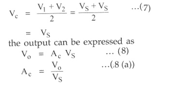
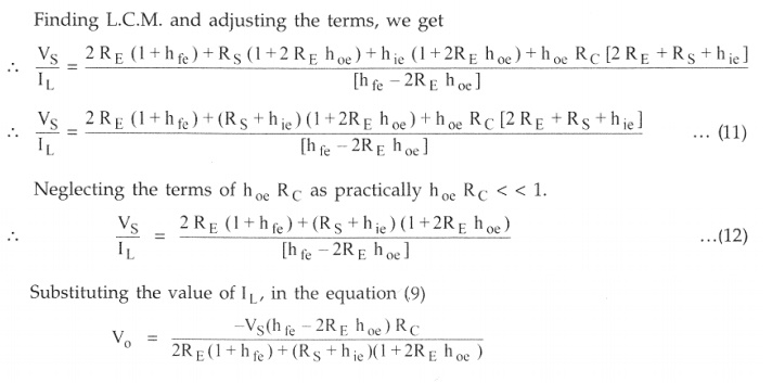
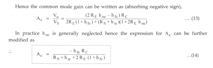
2. Common
Mode Gain (A C)
Let the
magnitude of both the a.c. input signals be VS and are in phase with each
other. Hence the differential input Vd = 0 while the common mode input Vc is
the average value of the two.
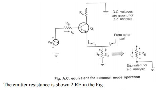
But now
both the emitter currents flows through R E in the Same direction.
Hence the total current flowing through R E is 2I e.
considering only one transistor, as in the Fig
Related Topics