Chapter: Transmission and Distribution : Structure of Power System
Types of D.C. Distributors
TYPES OF D.C. DISTRIBUTORS
The most general method of classifying d.c. distributors is the way they are fed by the feeders. On this basis, d.c. distributors are classified as:
( i) Distributor fed at one end
( ii) Distributor fed at both ends
( iii) Distributor fed at the centre
( iv) Ring distributor.
( i) Distributor fed at one end.
In this type of feeding, the distributor is connected to the supply at one end and loads are taken at different point along the length of the distributor.
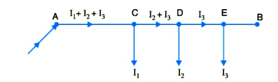
Fig. shows the single line diagram of a d.c. distributor A B fed at the end A (also known as singly fed distributor) and loads I1 , I2 and I3 tapped off at points C, D and E respectively.
The following points are worth noting in a singly fed distributor:
( a) The current in the various sections of the distributor away from feeding point goes on decreasing. Thus current in section AC is more than the current in section CD and current in section CD is more than the current in section DE.
( b) The voltage across the loads away from the feeding point goes on decreasing. Thus in Fig. the minimum voltage occurs at the load point E.
( c) In case a fault occurs on any section of the distributor, the whole distributor will have to be disconnected from the supply mains. Therefore, continuity of supply is interrupted.
( ii) Distributor fed at both ends.
In this type of feeding, the distributor is connected to the supply mains at both ends and loads are tapped off at different points along the length of the distributor. The voltage at the feeding points may or may not be equal. Fig. shows a distributor A B fed at the ends A and B and loads of I1 , I2 and I3tapped off at points C, D and E respectively.
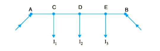
Here, the load voltage goes on decreasing as we move away from one feeding point say A , reaches minimum value and then again starts rising and reaches maximum value when we reach the other feeding point B. The minimum voltage occurs at some load point and is never fixed. It is shifted with the variation of load on different sections of the distributor.
Advantages
( a) If a fault occurs on any feeding point of the distributor, the continuity of supply is maintained from the other feeding point.
( b) In case of fault on any section of the distributor, the continuity of supply is maintained from the other feeding point.
( c) The area of X-section required for a doubly fed distributor is much less than that of a singly fed distributor.
( iii) Distributor fed at the centre.
In this type of feeding, the centre of the distributor is connected to the supply mains as shown in Fig. It is equivalent to two singly fed distributors, each distributor having a common feeding point and length equal to half of the total length.
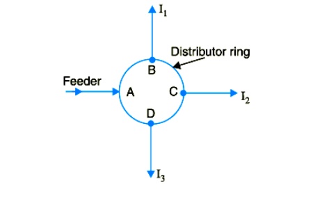
( iv)Ring mains.
In this type, the distributor is in the form of a closed ring as shown in Fig.It is equivalent to a straight distributor fed at both ends with equal voltages, the two ends being brought together to form a closed ring. The distributor ring may be fed at one or more than one point.
1. D.C. DISTRIBUTOR FED AT ONE END — CONCENTRATED LOADING
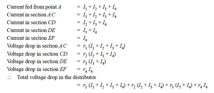
Fig. shows the single line diagram of a 2-wire d.c. distributor A B fed at one end A and having concentrated loads I1 , I2 , I3 and I4 tapped off at points C, D, E and F respectively.
Let r1 , r2 , r3 and r4 be the resistances of both wires (go and return) of the sections A C, CD, DE and EF of the distributor respectively
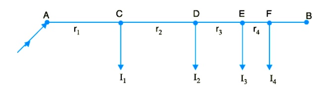
It is easy to see that the minimum potential will occur at point F which is farthest from the feeding point A .
2. UNIFORMLY LOADED DISTRIBUTOR FED AT ONE END
Fig shows the single line diagram of a 2-wire d.c. distributor A B fed at one end A and loaded uniformly with i amperes per metre length. It means that at every 1 m length of the distributor, the load tapped is i amperes. Let l metres be the length of the distributor and r ohm be the resistance per metre run.
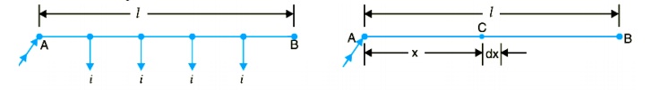
Consider a point C on the distributor at a distance x metres from the feeding point A as shown in Fig. Then current at point C is
= i l − i x amperes = i ( l − x) amperes
Now, consider a small length dx near point C. Its resistance is r dx and the voltage drop over length dx is d v = i ( l − x) r dx = i r ( l − x) dx Total voltage drop in the distributor upto point C is
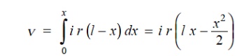
The voltage drop upto point B ( i.e. over the whole distributor) can be obtained by putting x = l in the above expression.
∴ Voltage drop over the distributor AB
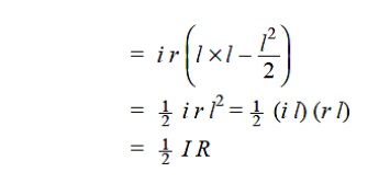
where
i l = I, the total current entering at point A r l = R, the total resistance of the distributor
Thus, in a uniformly loaded distributor fed at one end, the total voltage drop is equal to that produced by the whole of the load assumed to be concentrated at the middle point.
3. DISTRIBUTOR FED AT BOTH ENDS — CONCENTRATED LOADING
Whenever possible, it is desirable that a long distributor should be fed at both ends instead of at one end only, since total voltage drop can be considerably reduced without increasing the cross-section of the conductor. The two ends of the distributor may be supplied with ( i) equal voltages ( ii) unequal voltages.
( i) Two ends fed with equal voltages. Consider a distributor A B fed at both ends with equal voltages V volts and having concentrated loads I1 , I2 , I3 , I4 and I5 at points C, D, E, F and G respectively as shown in Fig. As we move away from one of the feeding points, say A , p.d. goes on decreasing till it reaches the minimum value at some load point, say E, and then again starts rising and becomes V volts as we reach the other feeding point B.
All the currents tapped off between points A and E (minimum p.d. point) will be supplied from the feeding point A while those tapped off between B and E will be supplied from the feeding point B.
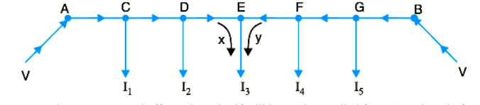
The current tapped off at point E itself will be partly supplied from A and partly from B. If these currents are x and y respectively, then,
I 3= x + y
Therefore, we arrive at a very important conclusion that at the point of minimum potential, current comes from both ends of the distributor.
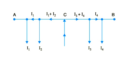
Point of minimum potential.
It is generally desired to locate the point of minimum potential. There is a simple method for it. Consider a distributor A B having three concentrated loads I1 , I2 and I3 at points C, D and E respectively. Suppose that current supplied by feeding end A is Ia . Then current distribution in the various sections of the distributor can be worked out as shown in Fig.
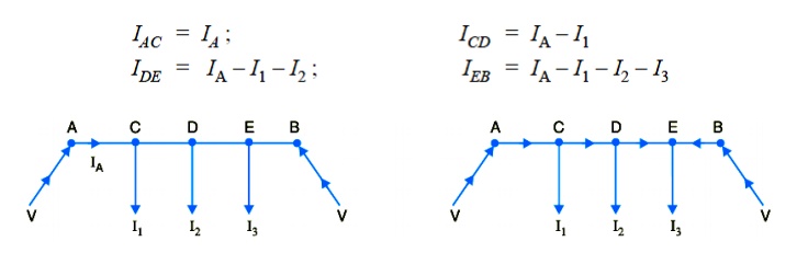
Voltage drop between A and B = Voltage drop over A B

From this equation, the unknown IA can be calculated as the values of other quantities are generally given. Suppose actual directions of currents in the various sections of the distributor are indicated as shown in Fig. The load point where the currents are coming from both sides of the distributor is the point of minimum potential i.e. point E in this case
( ii) Two ends fed with unequal voltages.
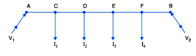
Fig. shows the distributor A B fed with unequal voltages end A being fed at V1 volts and end B at V2 volts. The point of minimum potential can be found by following the same procedure as discussed above. Thus in this case, Voltage drop between A and B = Voltage drop over A B
V1 − V2 = Voltage drop over A B
4. UNIFORMLY LOADED DISTRIBUTOR FED AT BOTH ENDS
We shall now determine the voltage drop in a uniformly loaded distributor fed at both ends. There can be two cases viz. the distributor fed at both ends with ( i) equal voltages ( ii) unequal voltages. The two cases shall be discussed separately.
( i) Distributor fed at both ends with equal voltages.
Consider a distributor A B of length l metres, having resistance r ohms per metre run and with uniform loading of i amperes per metre run as shown in Fig. 13.24. Let the distributor be fed at the feeding points A and B at equal voltages, say V volts. The total current supplied to the distributor is i l. As the two end voltages are equal, therefore, current supplied from each feeding point is i l/2 i.e.
Current supplied from each feeding point
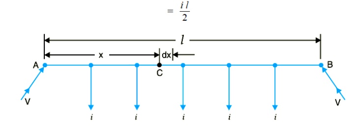
Consider a point C at a distance x metres from the feeding point A. Then current at point C is i l

Now, consider a small length dx near point C. Its resistance is r dx and the voltage drop over length dx is
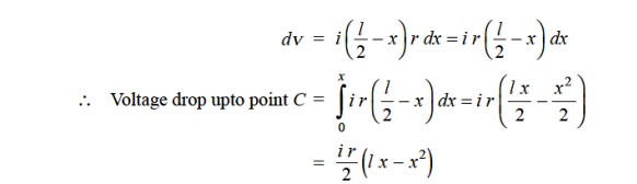
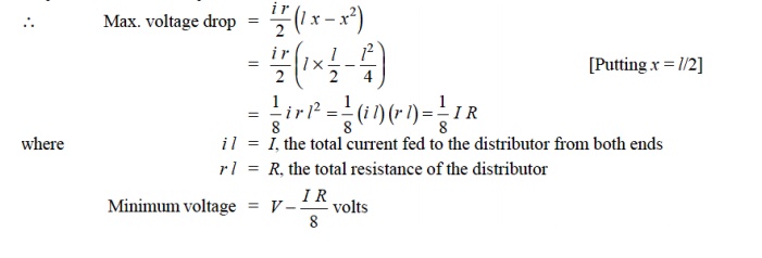
Obviously, the point of minimum potential will be the mid-point. Therefore, maximum voltage drop will occur at mid-point i.e. where x = l/2.
( ii) Distributor fed at both ends with unequal voltages.
Consider a distributor AB of length l metres having resistance r ohms per metre run and with a uniform loading of i amperes per metre run as shown in Fig. Let the distributor be fed from feeding points A and B at voltages VA and VB respectively. Suppose that the point of minimum potential C is situated at a distance x metres from the feeding point A. Then current supplied by the feeding point A will be * i x.
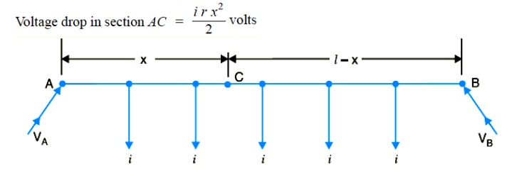
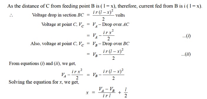
As all the quantities on the right hand side of the equation are known, therefore, the point on the distributor where minimum potential occurs can be calculated.
Related Topics