Chapter: Digital Electronics : Minimization Techniques and Logic Gates
Tristate Gates
TRISTATE GATES
Normally
when we have to implement shared bus systems inside an ASIC or externally to
the chip, we have two options: either to use a MUX/DEMUX based system or to use
a tri-state base bus system.
In the
latter, when logic is not driving its output, it does not drive LOW neither
HIGH, which means that logic output is floating. Well, one may ask, why not
just use an open collector for shared bus systems? The problem is that open
collectors are not so good for implementing wire-ANDs.
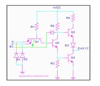
The
circuit below is a tri-state NAND gate; when Enable En is HIGH, it works like
any other NAND gate. But when Enable En is driven LOW, Q1 Conducts, and the
diode connecting Q1 emitter and Q2 collector, conducts driving Q3 into cut-off.
Since Q2 is not conducting, Q4 is also at cut-off. When both pull-up and
pull-down transistors are not conducting, output Z is in high-impedance state.
Related Topics