Chapter: Civil : Railway Airport Harbour Engineering : Railway Engineering : Modern Welded Railway Track
Track Structure for LWR(Long Welded Rails)
Track Structure for LWR
The minimum length required for a
rail to function as an LWR depends upon the range of temperature variation, the
section of the rail, the resistance offered by the ballast to the thermal
expansion of the sleepers, and the resistance offered by the rail and sleeper
assembly to any thermal expansion of the rails. Normally, a rail length of
about 100 m on BG and 150 m on MG is subjected to thermal expansion at each
rail end. Thus a length of more than 200 m on BG and 300 m on MG is generally
necessary for a welded rail panel to function as an LWR.
1 Formation
The formation should not pose any
problems in the laying of LWRs. In stretches where the formation is bad, it
should be stabilized before the LWRs are laid. A cross slope of 1 in 40 should
be provided at the time of screening and laying of LWRs. In the case of
concrete sleeper tracks, an extra cess width is provided to the extent of 90 cm
for embankments and 60 cm for cuttings.
2
Ballast
A clean ballast cushion of a
minimum depth of 250 mm (10") should be provided below the bottom of the
sleeper for LWRs. In order to increase resistance, the shoulder width of the
ballast should measure 350 mm in the case of straight tracks and the inside of
curves and 500 mm in the case of the outer ends of curves. The ballast should
also be humped to a height of 150 mm on both shoulders.
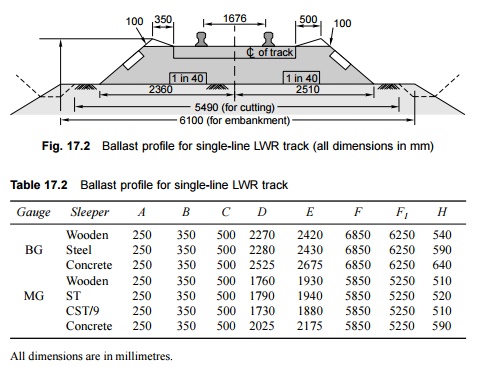
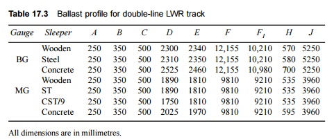
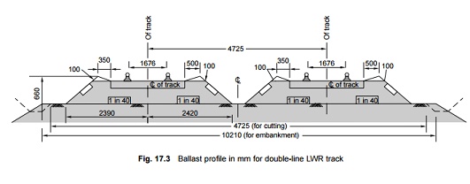
The
typical ballast profiles for LWRs for single-line and double-line BG concrete
sleeper tracks with a 250 mm (10") ballast cushion are given in Figs 17.2
and 17.3, respectively and are also, respectively, summarized in Tables 17.2 and
17.3.
If
followed by a non-LWR track, the ballast section and depth of the LWR track
should be continued over the switch expansion joint or buffer rail assembly and
also up to the rail lengths beyond it.
3 Sleepers Prescribed for LWR and CWR
The sleepers prescribed for LWR and CWR tracks are listed
below.
Broad gauge (BG)
(i) Concrete
sleepers with elastic fastenings.
(ii) Untreated
or hard (U category) wooden sleepers with fastenings for speeds not exceeding
160 km/h.
(iii) Steel
trough sleepers with elastic fastenings for speeds not exceeding
130 m/h
(as an interim measure for speeds up to 160 m/h).
However, as an interim measure,
steel trough sleepers with loose jaws and keys, untreated wooden sleepers, and
CST-9 sleepers are also permitted.
Sleeper density for BG On BG
tracks the sleeper density on LWR/CWR should be as follows:
GMT > 20 1660 sleepers per kilometre for all
routes except the E route, where 1540 sleepers per km may be permitted
For GMT 10-20 1660 sleepers per
kilometre for route A; 1540 per kilometre for routes B, C, D, and E
For GMT < 10 1660 sleepers per kilometre for
route A; 1540 per kilometre routes for B, C, and D, 1310 per kilometre for
route E (1540 per kilometre if LWRs is provided).
Meter gauge (MG)
The prescribed sleepers for MG
tracks are concrete sleepers, steel trough sleepers, durable wooden sleepers,
and CST-9 sleepers.
Sleeper density for MG On MG
tracks, the sleeper density should be 1540 sleepers per kilometre for
speeds up to 100 km/h and 1660 sleepers per kilometre for speeds above 100
km/h. On the existing LWR/CWR tracks, the decision to retain or change the
existing sleeper density is taken by the chief engineer.
4 Rails
LWRs should be laid with 60-kg,
52-kg, or 90 R rails on BG and 90 R or 75 R rails on MG barring the portions
already laid with 60 R rails. Generally, new rails with fish bolt holes should
not be used for LWRs. Further, level crossings should not fall within the
breathing lengths of LWRs and switch expansion joints or buffer rails should be
located at the end of the LWRs.
Related Topics