Chapter: Mechanical : Automobile Engineering : Engine Auxiliary Systems Ignition System
The Simple Carburetor
The Simple Carburetor
Carburetors are highly complex. Let us first understand the working principle bf a simple or elementary carburetor that provides an air fuel mixture for cruising or normal range at a single speed. Later, other mechanisms to provide for the various special requirements like starting, idling, variable load and speed operation and acceleration will be included. Figure 3. shows the details of a simple carburetor.
The simple carburetor mainly consists of a float chamber, fuel discharge nozzle and a metering orifice, a venturi, a throttle valve and a choke. The float and a needle valve system maintain a constant level of gasoline in the float chamber. If the amount of fuel in the float chamber falls below the designed level, the float goes down, thereby opening the fuel supply valve and admitting fuel. When the designed level has been reached, the float closes the fuel supply valve thus
stopping additional fuel flow from the supply system. Float chamber is vented either to the atmosphere or to the” upstream side of the venturi.During suction stroke air is drawn through the
venturi.
As already described, venturi is a tube of decreasing cross-section with a minimum area at the throat, Venturi tube is also known as the choke tube and is so shaped that it offers minimum resistance to the air flow. As the air passes through the venturi the velocity increases reaching a maximum at the venturi throat. Correspondingly, the pressure decreases reaching a minimum. From the float chamber, the fuel is fed to a discharge jet, the tip of which is located in the throat of the venturi. Because of the differential pressure between the float chamber and the throat of the venturi, known as carburetor depression, fuel is discharged into the air stream.
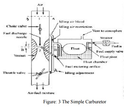
The fuel discharge is affected by the size of the discharge jet and it is chosen to give the required air-fuel ratio. The pressure at the throat at the fully open throttle condition lies between 4 to 5 cm of Hg, below atmospheric and seldom exceeds8 cm Hg below atmospheric. To avoid overflow of fuel through the jet, the level of the liquid in the float chamber is maintained at a level slightly below the tip of the discharge jet. This is called the tip of the nozzle. The difference in the height between the top of the nozzle and the float chamber level is marked h in Fig.3.
The gasoline engine is quantity governed, which means that when power output is to be varied at a particular speed, the amount of charge delivered to the cylinder is varied. This is achieved by means of a throttle valve usually of the butterfly type that is situated after the venturi tube.
As the throttle is closed less air flows through the venturi tube and less is the quantity of air-fuel mixture delivered to the cylinder and hence power output is reduced. As the” throttle is opened,
more air flows through the choke tube resulting in increased quantity of mixture being delivered to the engine. This increases the engine power output. A simple carburetor of the type described above suffers from a fundamental drawback in that it provides the required A/F ratio only at one throttle position.
At the other throttle positions the mixture is either leaner or richer depending on whether the throttle is opened less or more. As the throttle opening is varied, the air flow varies and creates a certain pressure differential between the float chamber and the venturi throat. The same pressure differential regulates the flow of fuel through the nozzle. Therefore, the velocity of flow of air II and fuel vary in a similar manner.
The Choke and the Throttle
When the vehicle is kept stationary for a long period during cool winter seasons, may be overnight, starting becomes more difficult. As already explained, at low cranking speeds and intake temperatures a very rich mixture is required to initiate combustion. Some times air-fuel ratio as rich as 9:1 is required. The main reason is that very large fraction of the fuel may remain as liquid suspended in air even in the cylinder. For initiating combustion, fuel-vapour and air in the form of mixture at a ratio that can sustain combustion is required.
It may be noted that at very low temperature vapour fraction of the fuel is also very small and this forms combustible mixture to initiate combustion. Hence, a very rich mixture must be supplied. The most popular method of providing such mixture is by the use of choke valve. This is simple butterfly valve located between the entrance to the carburetor and the venturi throat as shown in Fig.3.
When the choke is partly closed, large pressure drop occurs at the venturi throat that would normally result from the quantity of air passing through the venturi throat. The very large depression at the throat inducts large amount of fuel from the main nozzle and provides a very rich mixture so that the ratio of the evaporated fuel to air in the cylinder is within the combustible limits. Sometimes, the choke valves are spring loaded to ensure that large carburetor depression and excessive choking does not persist after the engine has started, and reached a desired speed.
This choke can be made to operate automatically by means of a thermostat so that the choke is closed when engine is cold and goes out of operation when engine warms up after starting. The speed and the output of an engine is controlled by the use of the throttle valve, which is located on the downstream side of the venturi.
The more the throttle is closed the greater is the obstruction to the flow of the mixture placed in the passage and the less is the quantity of mixture delivered to .the cylinders. The decreased quantity of mixture gives a less powerful impulse to the pistons and the output of the engine is reduced accordingly. As the throttle is opened, the output of the engine increases. Opening the throttle usually increases the speed of the engine. But this is not always the case as the load on the engine is also a factor. For example, opening the throttle when the motor vehicle is starting to climb a hill may or may not increase the vehicle speed, depending upon the steepness of the hill and the extent of throttle opening. In short, the throttle is simply a means to regulate the output of the engine by varying the quantity of charge going into the cylinder.
Compensating Devices
An automobile on road has to run on different loads and speeds. The road conditions play a vital role. Especially on city roads, one may be able to operate the vehicle between 25 to 60% of the throttle only. During such conditions the carburetor must be able to supply nearly constant air-fuel ratio mixture that is economical (16:1).However, the tendency of a simple carburetor is to progressively richen the mixture as the throttle starts opening.
The main metering system alone will not be sufficient to take care of the needs of the engine. Therefore, certain compensating devices are usually added in the carburetor along with the main metering system so as to supply a mixture with the required air-fuel ratio. A number of compensating devices are in use. The important ones are
i. Air-bleed jet
ii. Compensating jet
iii. Emulsion tube
iv.Back suction control mechanism
v. Auxiliary air valve
vi.Auxiliary air port
As already mentioned, in modern carburetors automatic compensating devices are provided to maintain the desired mixture proportions at the higher speeds. The type of compensation mechanism used determines the metering system of the carburetor. The principle of operation of various compensating devices are discussed briefly in the following sections.
Air-bleed jet
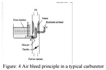
Figure 4. illustrates a principle of an air-bleed system in atypical modern downdraught carburetor. As could be seen it contains an air-bleed into the main nozzle. An orifice restricts the flow of air through this bleed and therefore it is called restricted air-bleed jet that is very popular. When the engine is not operating the main jet and the air bleed jet will be filled with fuel. When the engine starts, initially the fuel starts coming through the main as well as the air bleed jet (A). As the engine picks up, only air starts coming through the air bleed and mixes with fuel at B making a air fuel emulsion.
Thus the fluid stream that has become an emulsion of air and liquid has negligible viscosity
and surface tension. Thus the flow rate of fuel is augmented and more fuel is sucked at low suctions.
‘By proper design of hole size at B compatible with the entry hole at A, it is possible to maintain a fairly uniform mixture ratio for the entire power range of the operation of an engine. If the fuel flow nozzle of the air-bleed system is placed in the centre of the venturi, both the air-bleed nozzle and the venturi are subjected to same engine suction resulting approximately same fuel-air mixture for the entire power range of operation.
Compensating Jet
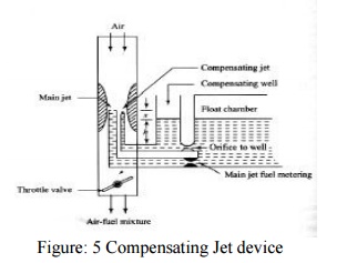
The principle of compensating jet device is to make the mixture leaner as the throttle opens progressively. In this method, as can be seen from Fig.5 in addition to the main jet, a compensating jet is incorporated. The compensating jet is connected to the compensation well. The compensating well is also vented to atmosphere like the main float chamber.
The compensating well is supplied with fuel from the main float chamber through a restricting orifice. With the increase in airflow rate, there is decrease of fuel level in the compensating well, with the result that fuel supply through the compensating jet decreases. The compensating jet thus progressively makes the mixture leaner as the main jet progressively makes the mixture richer. The main jet curve and the compensating jet curve are more or less reciprocals of each other.
Emulsion Tube
The mixture correction is attempted by air bleeding in modern carburetor. In one such arrangement as shown in Fig.6, the main metering jet is kept at a level of about 25 mm below the fuel level in the float chamber. Therefore, it is also called submerged jet. The jet is located at the bottom of a well. The sides of the well have holes. As can be seen from the figure these holes are in communication with the atmosphere. In the beginning the level of petrol in the float chamber and the well is the same.
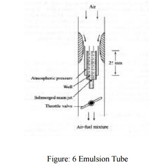
When the throttle is opened the pressure at the venturi throat decreases and petrol is drawn into the air stream. This results in progressively uncovering the holes in the central tube leading to increasing air-fuel ratios or decreasing richness of mixture when all holes have been uncovered. Normal flow takes place from the main jet. The air is drawn through these holes in the well, and the fuel is emulsified and the pressure differential across the column of fuel is not as high as that in simple carburetor.
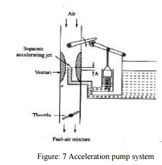
Acceleration Pump System
Acceleration is a transient phenomenon. In order to accelerate the vehicle and consequently its engine, the mixture required is very rich and the richness of the mixture has to be obtained quickly and very rapidly. In automobile engines situations arise when it is necessary to accelerate the vehicle. This requires an increased output from the engine in a very short time.
If the throttle is suddenly opened there is a corresponding increase in the air flow. However, because of the inertia of the liquid fuel, the fuel flow does not increase in proportion to the increase in air flow. This results in a temporary lean mixture ca11singtheengine to misfire and a temporary reduction in power output.
To prevent this condition, all modern carburetors are equipped with an accelerating system. Figure 7. illustrates simplified sketch of one such device. The pump comprises of a spring loaded plunger that takes care of the situation with the rapid opening of the throttle valve. The plunger moves into the cylinder and forces an additional jet of fuel at the venturi throat.
When the throttle is partly open, the spring sets the plunger back. There is also an arrangement which ensures that fuel in the pump cylinder is not forced through the jet when valve is slowly opened or leaks past the plunger or some holes into the float chamber.
Mechanical linkage system, in some carburetor, is substituted by an arrangement where by the pump plunger is held up by manifold vacuum. When this vacuum is decreased by rapid opening of the throttle, a spring forces the plunger down pumping the fuel through the jet.
Related Topics