Chapter: Digital Electronics : Sequential Circuits
Synchronous Counter
SYNCHRONOUS COUNTER:
There is a problem with the ripple counter just discussed. The output stages of the flip-flops further down the line (from the first clocked flip-flop) take time to respond to changes that occur due to the initial clock signal. This is a result of the internal propagation delay that occurs within a given flip-flop.
A standard TTL flip-flop may have an internal propagation delay of 30 ns. If you join four flip-flops to create a MOD-16 counter, the accumulative propagation delay at the highest-order output will be 120 ns. When used in high-precision synchronous systems, such large delays can lead to timing problems.
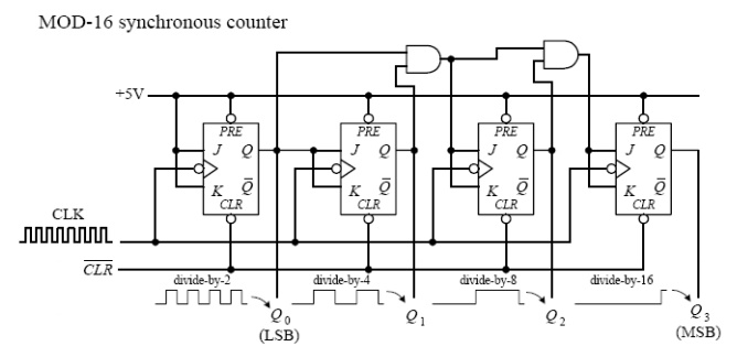
To avoid large delays, you can create what is called a synchronous counter. Synchronous counters, unlike ripple (asynchronous) counters, contain flip-flops whose clock inputs are driven at the same time by a common clock line. This means that output transitions for each flip-flop will occur at the same time. Now, unlike the ripple counter, you must use some additional logic circuitry placed between various flip-flop inputs and outputs to give the desired count waveform.
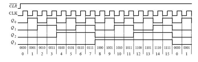
For example, to create a 4-bit MOD-16 synchronous counter requires adding two additional AND gates, as shown below. The AND gates act to keep a flip-flop in hold mode (if both input of the gate are low) or toggle mode (if both inputs of the gate are high). So, during the 0–1 count, the first flip-flop is in toggle mode (and always is); all the rest are held in hold mode. When it is time for the 2–4 count, the first and second flip-flops are placed in toggle mode; the last two are held in hold mode.
When it is time for the 4–8 count, the first AND gate is enabled, allowing the the third flip-flop to toggle. When it is time for the 8–15 count, the second AND gate is enabled, allowing the last flip-flop to toggle. You can work out the details for yourself by studying the circuit and timing waveforms.
The ripple (asynchronous) and synchronous counters discussed so far are simple but hardly ever used. In practice, if you need a counter, be it ripple or synchronous, you go out and purchase a counter IC. These ICs are often MOD-16 or MOD-10 counters and usually come with many additional features. For example, many ICs allow you to preset the count to a desired number via parallel input lines. Others allow you to count up or to count down by means of control inputs. I will talk in great detail about counter ICs in a moment.
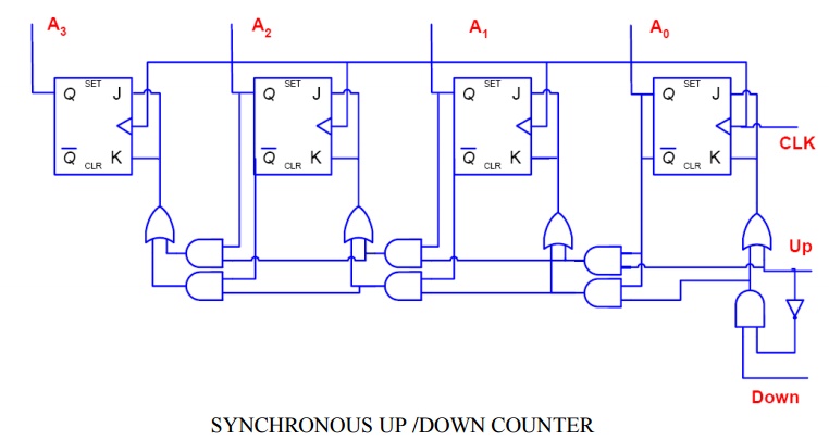
1. SYNCHRONOUS UP /DOWN COUNTER:
The down counter counts in reverse from 1111 to 0000 and then goes to 1111. If we inspect the count cycle, we find that each flip-flop will complement when the previous flip-flops are all 0 (this is the opposite of the up counter). The down counter can be implemented similar to the up counter, except that the AND gate input is taken from Q’ instead of Q. This is shown in the following Figure of a 4-bit up-down counter using T flip-flops.
Related Topics