Chapter: Civil : Railway Airport Harbour Engineering : Railway Engineering : Curves and Superelevation
Railway Engineering:Transition Curve

Transition Curve
As soon as a train commences
motion on a circular curve from a straight line track, it is subjected to a
sudden centrifugal force, which not only causes discomfort to the passengers
but also distorts the track alignment and affects the stability of the rolling
stock. In order to smoothen the shift from the straight line to the curve,
transition curves are provided on either side of the circular curve so that the
centrifugal force is built up gradually as the superelevation slowly runs out
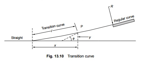
at a uniform rate (Fig. 13.10). A transition curve is, therefore, the cure for
an uncomfortable ride, in which the degree of the curvature and the gain of
superelevation are uniform throughout its length, starting from zero at the
tangent point to the specified value at the circular curve. The following are
the objectives of a transition curve.
(a) To
decrease the radius of the curvature gradually in a planned way from infinity
at the straight line to the specified value of the radius of a circular curve
in order to help the vehicle negotiate the curve smoothly.
(b) To
provide a gradual increase of the superelevation starting from zero at the
straight line to the desired superelevation at the circular curve.
(c) To ensure
a gradual increase or decrease of centrifugal forces so as to enable the
vehicles to negotiate a curve smoothly.
1 Requirements of an Ideal Transition
Curve
The transition curve should satisfy the following conditions.
(a) It should
be tangential to the straight line of the track, i.e., it should start from the
straight part of the track with a zero curvature.
(b) It should
join the circular curve tangentially, i.e., it should finally have the same
curvature as that of the circular curve.
(c) Its
curvature should increase at the same rate as the superelevation.
(d) The
length of the transition curve should be adequate to attain the final
superelevation, which increases gradually at a specified rate.
2 Types of Transition Curves
The types
of transition curves that can be theoretically provided are described here. The
shapes of these curves are illustrated in Fig. 13.11.
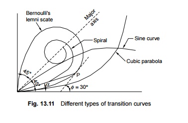
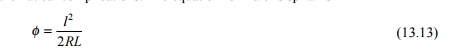
Euler's spiral This is an ideal transition curve, but is
not preferred due to mathematical complications. The equation for Euler's
sprial is
Cubical spiral This is also a good transition curve, but
quite difficult to set on the field.
Bernoulli's lemniscate In this
curve, the radius decreases as the length increases and this causes the
radial acceleration to keep on falling. The fall is, however, not uniform
beyond a 30 o deflection angle. This curve is not used on railways.
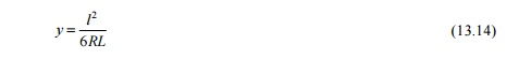
Cubic
parabola Indian Railways mostly uses the cubic parabola for transition
curves. The equation of the cubic parabola is
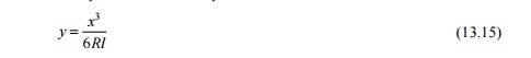
In this curve, both the curvature
and the cant increase at a linear rate. The cant of the transition curve from
the straight to the curved track is so arranged that the inner rail continues
to be at the same level while the outer rail is raised in the linear form
throughtout the length of the curve. A straight line ramp is provided for such
transition curves.
The notations used in Eqns
(13.13) to (13.15) are as follows: f is the
angle between the straight line track and the tangent to the transition curve, l
is the distance of any point on the transition curve from the take-off point, L
is the length of the transition curve, x is the horizontal coordinate on
the transition curve, y is the vertical coordinate on the transition
curve, and R is the radius of the circular curve.
S-shaped
transition curve In an S-shaped transition curve, the curvature and
superelevation assume the shape of two quadratic parabolas. Instead of a straight
line ramp, an S-type parabola ramp is provided with this transition curve. The
special feature of this curve is that the shift required ('shift' is explained
in the following section) in this case is only half of the normal shift
provided for a straight line ramp. The value of shift is
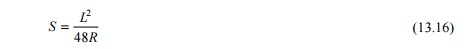
Further, the gradient is at the
centre and is twice steeper than in the case of a straight line ramp. This
curve is desirable in special conditions-when the shift is restricted due to
site conditions.
The
Railway Board has decided that on Indian Railways, transition curves will
normally be laid in the shape of a cubic parabola.
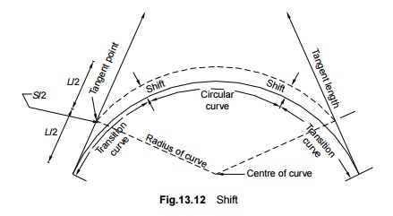
3 Shift
For the
main circular curve to fit in the transition curve, which is laid in the shape
of a cubic parabola, it is required be moved inward by a measure known as the
'shift' (Fig. 13.12). The value of shift can be calculated using the formula
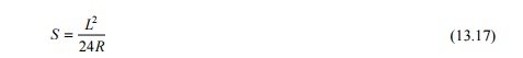
where S
is the shift in m, L is the length of the transition curve in m, and R
is the radius in m.
The
offset (in centimetres) from the straight line to any point on the transition
curve is calculated using the equation.
y = 16.7 x2/LR
where y is the offest from
the staight line in cm, x is the distance from the commencement of the
curve in m, L is the length of transition in m, and R is the
radius of curve in m.
4 Length of Transition Curve
The
length of the transition curve prescribed on Indian Railways is the maximum of
the following three values:
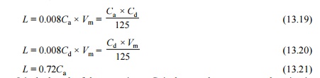
where L
is the length of the curve in m, Ca is the actual cant or
superelevation in mm, and Cd is the cant deficiency in mm.
Formulae (13.19) and (13.20) are
based on a rate of change of a cant or cant deficiency of 35 mm/sec. Formula
(13.21) is based on a maximum cant gradient of 1 in a 720 or 1.4 mm/m.
Other provisions made to meet the
requirements of special situations are as follows.
(a) When
deciding the length of transition curves, particularly on high-speed routes,
future speeds expected to be implemented on those tracks, such as 160 km/h for
group A routes and 130 km/h for group B routes, may be taken into account.
(b) In
exceptional cases, when there is no space available for providing full length
transition curves, particularly on high-speed routes as per the preceding
calculations, the length of the transition curve may be reduced to two-thirds
of the desirable length as worked out by Eqns (13.19) and (13.20). This is
based on the assumption that the rate of change of cant or cant deficiency will
not exceed 55 mm/sec and the maximum cant gradient will not be steeper than 1
in 360 or 2.8 mm/m. This relaxation is permitted only for BG sections. For MG
and NG sections, however, the cant gradient should not be steeper than 1 in 720
or 1.4 mm/h. For MG sections, the change of cant or cant deficiency should not
exceed 35 mm/sec.
(c) At
locations where the length of the transition curve is restricted and as such
may be inadequate to permit the maximum speed calculated for the circular
curve, the design should be such that both the cant and the cant deficiency are
lowered, which will reduce the maximum speed on the transition curve to permit
the highest speed on the curve as a whole.
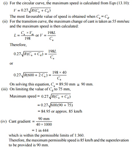
Example 13.6 A curve
of 600 m radius on a BG section has a limited transition of 40 m length.
Calculate the maximum permissible speed and superelevation for the same. The
maximum sectional speed (MSS) is 100 km/h.
Solution In a
normal situation, a curve of a 600 m radius will have quite a long transition
curve for an MSS of 100 km/h. However, as the transition curve has been
restricted to 40 m, the cant should be so selected that the speed on the main
circular curve is equal to the speed on the transition curve as a whole.
5 Laying a Transition Curve
A
transition curve is laid in the following steps (Fig. 13.13).
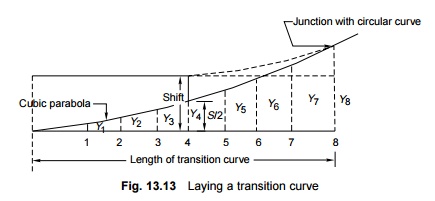
1. The
length of the transition curve is calculated by the formulae given in Eqns
(13.19) to (13.21).
2. This
transition length is divided into an even number of equal parts, usually eight.
3. The
equations for a cubic parabola and the shift [Eqns (13.15) and (13.17)],
reproduced here, are used for calculations.
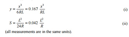
4. The shift
is calculated using Formula (ii).
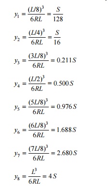
5. The
ordinates are then calculated at points 1, 2, 3, etc. using Formula (i).
6. The point
at which the transition curve starts is then determined approximately by
shifting the existing tangent point backwards by distance equal to half the
length of the transition curve.
7. The offsets y1, y2, y3, etc. are measured perpendicular to the tangent to get the profile of the transition curve.
Related Topics