Chapter: Civil : Railway Airport Harbour Engineering : Railway Engineering : Curves and Superelevation
Railway Engineering: Compound and Reverse Curve
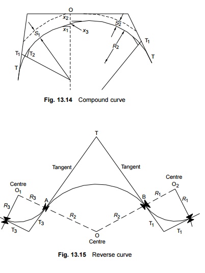
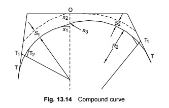
Compound Curve
A compound curve (Fig. 13.14) is formed by the combination of two circular curves of different radii curving in the same direction. A common transition curve may be provided between the two circular curves of a compound curve. Assuming that such a connecting curve is to be traversed at a uniform speed, the length of the transition curve connecting the two circular curves can be obtained from the formula
where Ca1 and Cd1 are the
cant and cant deficiency for curve 1 and Ca2 and Cd2
are the cant and cant deficiency for curve 2 in millimetres. L is the
length of the transition curve, in m,and Vm is the maximum
permissible speed in km/h.
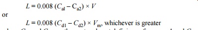
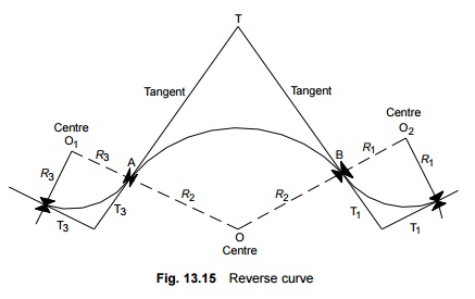
Reverse Curve
A reverse curve (Fig. 13.15) is formed by the combination of
two circular curves with opposite curvatures. A common transition curve may be
provided between the two circular curves of a reverse curve. The total length
of the transition curve, from the common circular curve to the individual
circular curve, may be obtained in the same manner as explained for a compound
curve in Section 13.15.
It has been stipulated that for
high-speed group A and B routes, a minimum straight length of 50 m should be
kept between the two curves constituting a reverse curve. In the case of a
high-speed MG route, the distance to be kept should be 30 m. Straight lines
between the circular curves measuring less than 50 m on BG sections of group A
and B routes and less than 30 m on high-speed MG routes should be eliminated by
suitably extending the transition lengths. When doing so, it should be ensured
that the rate of change of cant and versine along the two transition lengths
being extended is kept the same. When such straight lines between reverse
curves cannot be eliminated and their lengths cannot be increased to over 50 m
in the case of BG routes and 30 m in the case of MG routes, speeds in excess of
130 km/h on BG routes and 100 km/h on MG routes should not be permitted.
Related Topics