Chapter: Microprocessor and Microcontroller : I/O Interfacing
Programmable timer device 8253
Programmable timer device 8253
Intel’s programmable counter/timer device (8253) facilitates the generation of accurate time delays. When 8253 is used as timing and delay generation peripheral, the microprocessor becomes free from the tasks related to the counting process and execute the programs in memory, while the timer device may perform the counting tasks. This minimizes the software overhead on the microprocessor.
ü Architecture
and Signal Descriptions
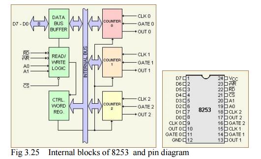
The
programmable timer device 8253 contains three independent 16-bit counters, each
with a maximum count rate of 2.6 MHz to generate three totally independent
delays or maintain three independent counters simultaneously. All the three
counters may be independently controlled by programming the three internal
command word registers.
ü The 8-bit, bidirectional data buffer interfaces internal circuit of 8253
to microprocessor systems bus. Data
is transmitted or received by the buffer upon the execution of IN or OUT
instruction. The read/write logic controls the direction of the data buffer
depending upon whether it is a read or a write operation. It may be noted that
IN instruction reads data while OUT instruction writes data to a peripheral.
ü The three counters all 16-bit
presettable, down counters, able to operate either in BCD or in hexadecimal mode. The mode control word register contains the
information that can be used for writing or reading the count value into or
from the respective count register using the OUT and IN instructions. The
specialty of the 8253 counters is that they can be easily read on line without
disturbing the clock input to the counter. This facility is called as "on
the fly" reading of counters, and is invoked using a mode control word.
ü A0, Al pins are the address input pins and are required internally for
addressing the mode control word registers and
the three counter registers. A low on CS line enables the 8253. No operation
will be performed by 8253 till it is enabled.
Table 3.1
selected operations for various Control

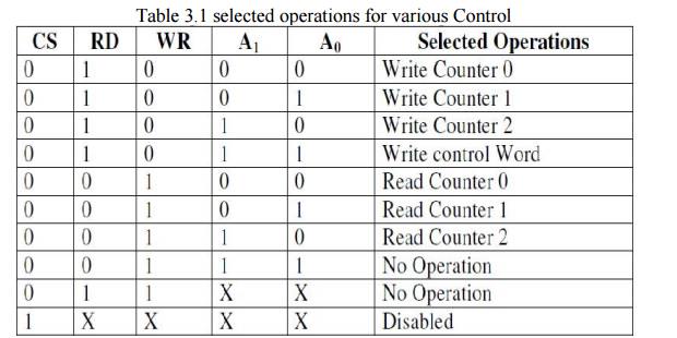
A control
word register accepts the 8-bit control word written by the microprocessor and
stores it for controlling the complete operation of the specific counter. It
may be noted that, the control word register can only be written and cannot be
read as it is obvious from Table
.The CLK,
GATE and OUT pins are available for each of the three timer channels. Their
functions will be clear when we study the different operating modes of 8253.
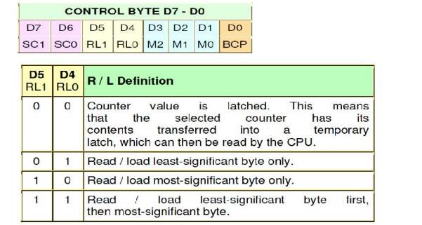
ü Control
Word Register
The 8253
can operate in anyone of the six different modes. A control word must be
written in the respective control word register by the microprocessor to
initialize each of the counters of 8253 to decide its operating mode. All the
counters can operate in anyone of the modes or they may be even in different
modes of operation, at a time.
The
control word format is presented, along with the definition of each bit, while
writing a count in the counter, it should be noted that, the count is written
in the counter only after the data is put on the data bus and a falling edge
appears at the clock pin of the peripheral thereafter. Any reading operation of
the counter, before the falling edge appears may result in garbage data.
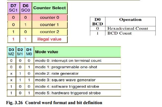
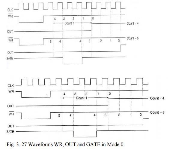
MODE 0 This mode of operation is called
as interrupt on terminal count. In this mode,
the output is initially low after the mode is set. The output remains low even
after the count value is loaded in the counter. The counter starts decrementing
the count value after the falling edge of the clock, if the GATE input is high.
The process of decrementing the counter continues at each falling edge of the
clock till the terminal count is reached, i.e. the count becomes zero. When the
terminal count is reached, the output goes high and remains high till the
selected control word register or the corresponding count register is reloaded
with a new mode of operation or a new count, respectively.
This high
output may be used to interrupt the processor whenever required, by setting
suitable terminal count. Writing a count register while the previous counting
is in process, generates the following sequence of response.
The first
byte of the new count when loaded in the count register, stops the previous
count. The second byte when written, starts the new count, terminating the
previous count then and there. The GATE signal is active high and should be
high for normal counting. When GATE goes low counting is terminated and the
current count is latched till the GATE again goes high.
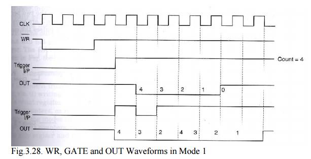
MODE 1 This mode of operation of 8253 is
called as programmable one-shot mode. the
8253 can be used as a monostable multivibrator. The duration of the quasistable state of the monstable
multivibrator is decided by the count loaded in the count register.
The gate
input is used as trigger input in this mode of operation. Normally the output
remains high till the suitable count is loaded in the count register and a
trigger is applied. After the application of a trigger (on the positive edge),
the output goes low and remains low till the count becomes zero. If another
count is loaded when the output is already low, it does not disturb the
previous count till a new trigger pulse is applied at the GATE input. The new
counting starts after the new trigger pulse.
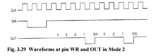
MODE 2 This mode is called either rate
generator or divide by N counter. In this
mode, if N is loaded as the count value, then, after N pulses, the output
becomes low only for one clock cycle. The count N is reloaded and again the output becomes high and remains high
for N clock pulses.
The
output is normally high after initialisation or even a low signal on GATE input
can force the output high. If GATE goes high, the counter starts counting down
from the initial value. The counter generates an active low pulse at the output
initially, after the count register is loaded with a count value. Then count
down starts and whenever the count becomes zero another active low pulse is
generated at the output.
The
duration of these active low pulses are equal to one clock cycle. The number of
input clock pulses between the two low pulses at the output is equal to the
count loaded. Figure shows the related waveforms for mode 2. Interestingly, the
counting is inhibited when GATE becomes low.
MODE 3 In this mode, the 8253 can be
used as a square wave rate generator. In
terms of operation this mode is somewhat similar to mode 2. When, the count
N loaded is even, then for half of
the count, the output remains high and for the remaining half it remains low.
If the
count loaded is odd, the first clock pulse decrements it by 1 resulting in an
even count value (holding the output high). Then the output remains high for
half of the new count and goes low for the remaining half. This procedure is
repeated continuously resulting in the generation of a square wave.
In case
of odd count, the output is high for longer duration and low for shorter
duration. The difference of one clock cycle duration between the two periods is
due to the initial decrementing of the odd count. The waveforms for mode 3 are
shown in Fig. if the loaded count value 'N
is odd, then for (N+l)/2 pulses the output remains high and for (N-l)/2 pulses
it remains low.
MODE 4 This mode of operation of 8253 is
named as software triggered strobe. After
the mode is set, the output goes high. When a count is loaded, counting down
starts. On terminal count, the output goes low for one clock cycle, and then it
again goes high. This low pulse can be used as a strobe, while interfacing the
microprocessor with other peripherals.
The count
is inhibited and the count value is latched, when the GATE signal goes low. If
a new count is loaded in the count register while the previous counting is in
the next clock cycle. The counting then proceeds according to the new count.
MODE 5 This mode of operation also
generates a strobe in response to the rising edge at the trigger input. This mode may be used to generate a delayed
strobe in response to an externally generated signal. Once this mode is
programmed and the counter is loaded, the output goes high.
The
counter starts counting after the rising edge of the trigger input (GATE). The
output goes low for one clock period, when the terminal count is reached. The
output will not go low until the counter content becomes zero after the rising
edge of any trigger. The GATE input in this mode is used as trigger input. The
related waveforms are shown in Fig. 1.8.
ü Programming
and Interfacing 8253
There may
be two types of write operations in 8253, viz.
(i) writing a
control word into a control word register and
(ii) writing a
count value into a count register.
The
control word register accepts data from the data buffer and initializes the
counters, as required. The control word register contents are used for (a)
initialising the operating modes (mode0-mode4) (b) selection of counters
(counter0-counter2) (c) choosing binary BCD counters (d) loading of the counter
registers.
The mode
control register is a write only register and the CPU cannot read its contents.
One can directly write the mode control word for counter 2 or counter 1 prior
to writing the control word for counter0. Mode control word register has a
separate address, so that it can be written independently. A count register
must be loaded with the count value with same byte sequence that was programmed
in the mode control word of that counter, using the bits RL0 and RL1.
The
loading of the count registers of different counters is again sequence
independent. One can directly write the 16-bit count register for count 2
before writing count 0 and count 1, but the two bytes in a count must be
written in the byte sequence programmed using RL0 and RL1 bits of the mode
control word of the counter. All the counters in 8253 are down counters, hence
their count values go on
decrementing
if the CLK input pin is applied with a valid clock signal. A maximum count is
obtained by loading all zeros into a count register, i.e. 216 for binary
counting and 104 for BCD counting. The 8253 responds to the negative clock edge
of the clock input.
The
maximum operating clock frequency of 8253 is 2.6 MHz. For higher frequencies
one can use timer 8254, which operates up to 10 MHz, maintaining pin
compatibility with 8253. The following Table 6.2 shows the selection of
different mode control words and counter register bytes depending upon address
lines Ao and A1
In 8253,
the 16-bit contents of the counter can simply be read using successive 8-bit IN
operations. As stated earlier, the mode control register cannot be read for any
of the counters. There are two methods for reading 8253 counter registers.
In the
first method, either the clock or the counting procedure (using GATE) is
inhibited to ensure a stable count. Then the contents are read by selecting the
suitable counter using A0, Al and executing using IN instructions. The first IN
instruction reads the least significant byte and the second IN instruction
reads the most significant byte. Internal logic of 8253 is designed in such a
way that the programmer has to complete the reading operation as programmed by
him, using RL0 and RLl bits of control word.
In the
second method of reading a counter, the counter can be read while counting is
in progress. This method, as already mentioned is called as reading on fly. In this method, neither clock nor the
counting needs to be inhibited to read the counter. The content of a counter
can be read 'on fly' using a newly defined control word register format for
online reading of the count register. Writing a suitable control word, in the
mode control register internally latches the contents of the counter. The
control word
format
for 'read on fly' mode is given in Fig. 1.9 along with its bit definitions.
After latching the content of a counter using this method, the programmer can
read it using IN instructions, as discussed before.
Related Topics