Chapter: Electrical machines : Starting and Speed Control of Three Phase Induction Motor
Pole changing method - Speed control of Three Phase Induction Motors
Pole changing method
Sometimes induction machines have a special stator winding capable of being externally connected to form two different number of pole numbers. Since the synchronous speed of the induction machine is given by ns = fs/p (in rev. /s) where p is the number of pole pairs, this would correspond to changing the synchronous speed. With the slip now corresponding to the new synchronous speed, the operating speed is changed. This method of speed control is a stepped variation and generally restricted to two steps.
If the changes in stator winding connections are made so that the air gap flux remains constant, then at any winding connection, the same maximum torque is achievable. Such winding arrangements are therefore referred to as constant-torque connections. If however such connection changes result in air gap flux changes that are inversely proportional to the synchronous speeds, then such connections are called constant-horsepower type.
The following figure serves to illustrate the basic principle. Consider a magnetic pole structure consisting of four pole faces A, B, C, D as shown in Fig: 3.31.
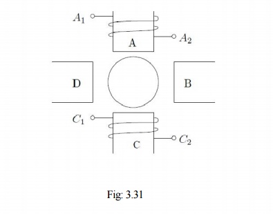
Coils are wound on A & C in the directions shown. The two coils on A & C may be connected in series in two different ways — A2 may be connected to C1 or C2. A1 with the Other terminal at C then form the terminals of the overall combination. Thus two connections result as shown in Fig: 3.32 (a) & (b).
Now, for a given direction of current flow at terminal A1, say into terminal A1, the flux directions within the poles are shown in the figures. In case (a), the flux lines are out of the pole A (seen from the rotor) for and into pole C, thus establishing a two-pole structure. In case (b) however, the flux lines are out of the poles in A & C. The flux lines will be then have to complete the circuit by flowing into the pole structures on the sides. If, when seen from the rotor, the pole emanating flux lines is considered as North Pole and the pole into which they enter is termed as south, then the pole configurations produced by these connections is a two-pole arrangement in Fig: 3.32(a) and a four-pole arrangement in Fig: 3.32 (b).

Thus by changing the terminal connections we get either a two pole air-gap field or a four- pole field. In an induction machine this would correspond to a synchronous speed reduction in half from case (a) to case (b). Further note that irrespective of the connection, the applied voltage is balanced by the series addition of induced emf s in two coils. Therefore the air-gap flux in both cases is the same. Cases (a) and (b) therefore form a pair of constant torque connections.
Consider, on the other hand a connection as shown in the Fig: 3.32 (c). The terminals T1 and T2 are where the input excitation is given. Note that current direction in the coils now resembles that of case (b), and hence this would result in a four-pole structure. However, in Fig: 3.32 (c), there is only one coil induced emf to balance the applied voltage. Therefore flux in case (c) would therefore be halved compared to that of case (b) or case (a), for that matter). Cases (a) and (c) therefore form a pair of constant horse-power connections.
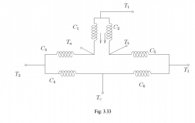
It is important to note that in generating a different pole numbers, the current through one coil (out of two, coil C in this case) is reversed. In the case of a three phase machine, the following example serves to explain this. Let the machine have coils connected as shown [C1 C6] as shown in Fig:
The current directions shown in C1 & C2 correspond to the case where T1, T2, T3 are supplied with three phase excitation and Ta, Tb &Tc are shorted to each other (STAR point). The applied voltage must be balanced by induced emf in one coil only (C1 & C2 are parallel). If however the excitation is given to Ta, Tb &Tc with T1, T2, T3 open, then current through one of the coils (C1 & C2) would reverse. Thus the effective number of poles would increase, thereby bringing down the speed. The other coils also face similar conditions.
Related Topics