Chapter: Civil : Structural Analysis : Plastic Analysis Of Structures
Plastic Analysis Of Structures
PLASTIC ANALYSIS OF STRUCTURES
1. Statically indeterminate axial problems
In these analyses we used
superposition often, knowing that for a linearly elastic structure it was valid.
However, an elastic analysis does not give information about the loads that will
actually collapse a structure. An indeterminate structure may sustain loads
greater than the load that first causes a yield to occur at any point in the structure.
In fact, a structure will stand as
long as it is able to find redundancies to yield. It is only when a structure has
exhausted all of its redundancies will extra load causes it to fail. Plastic analysis
is the method through which the actual failure load of a structure is
calculated, and as will be seen, this failure load can be significantly greater
than the elastic load capacity.
To summarize this, Prof. Seande Courcy
(UCD) used to say: 'a structure only collapses when it
has exhausted all means of standing'.
Before analyzing complete structures,
we review material and cross section behavior beyond the elastic limit.
2. Beams in pure bending
2.1. Material Behavior
Auniaxial tensile stress on a ductile
material
such as mild steel typically
provides the following graph of stress versus strain:
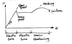
As can be seen, the material can sustain
strains farinexcess of the strain at which yield occurs before failure. This
property of the material is called its ductility. Though complex models do
exist to accurately reflect the above real behavior of the material, the most common,
and simplest, model is the idealized stress-strain curve. This is the curve for
an ideal elastic-plastic material (which doesn't exist),
and the graph is:
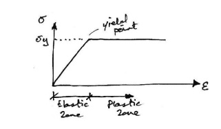
As can be seen, once the yield has
been reached it is taken that an indefinite amount of strain can occur. Since so
much post-yield strain is modeled, the actual material (or cross section) must also
be capable of allowing such strains. That is, it must be sufficiently ductile for
the idealized stress-strain curve to bevalid. Next we consider the behavior of
across section of an ideal elastic-plastic material subject to bending. In
doing so, we seek the relationship between applied moment and the rotation (or more
accurately, the curvature) of across section.
2.2. Moment-Rotation Characteristics of General Cross
Section
We consider an arbitrary cross-section
with a vertical plane of symmetry, which is also the plane of loading. We consider
the cross section subject to an increasing bending moment, and assess the stresses
at each stage.
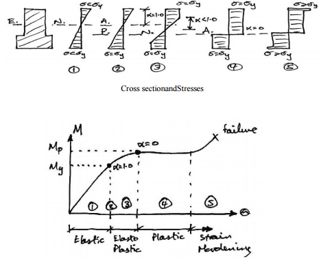
Stage1- Elastic Behaviour
The applied moment causes
stresses over the cross-section that are all less than the yield stress of the material.
Stage2-Yield Moment
The applied moment is just sufficient
that the yield stress of the material is reached at the outer most fibre(s) of the
cross-section. All other stresses in the cross section are less than the yield stress.
This is limit of applicability of an elastic analysis and of elastic design. Since
all fibres are elastic, the ratio of the depth of the elastic to plastic regions,
Stage3- Elasto-Plastic
Bending
The moment applied to the cross section
has been increased beyond the yield moment. Since by the idealized stress-strain
curve the material cannot sustain a stress greater than yield stress, the
fibres at the yield stress have progressed inwards towards the centre of the beam.
Thus over the cross section the reisanelastic core and a plastic region. The ratio
of the depth of the elastic core to the plastic region is .
Since extra moment is being applied
and no stress is bigger than the yield stress, extra rotation of the section occurs: the moment-rotation curve losses
its linearity and curves, giving more rotation per unit moment (i.e. looses stiffness).
Stage4- Plastic Bending
The applied moment to the cross section
is such that all fibres in the cross section are at yield stress. This is termed
the Plastic Moment Capacity of the section since there are no fibres at an
elastic stress, Also note that the full plastic moment requires an infinite strain
at the neutral axis
And so is physically impossible to
achieve. However, it is closely approximated in practice. Any attempt at increasing
the moment at this points imply results in more rotation, once the cross-section
has sufficient ductility. There fore in steel members the cross section classification
must be plastic and in concrete members the section must be under-reinforced.
Stage5-Strain Hardening
Due to strain hardening of the material, a small amount of extra
moment can be sustained.
The above moment-rotation curve represents
the behavior of across section of a regular elastic-plastic material. However, it
is usually further simplified as follows:
With this idealized moment-rotation
curve, the cross section linearly sustains moment up to the plastic moment capacity
of the section and then yields in rotation an indeterminate amount. Again, to use
this idealization, the actual section must be capable of sustaining large rotations- that is it
must be ductile.
Analysis of Rectangular Cross Section
Since we now know that across
section can sustain more load than just the yield moment, we are interested in how
much more. In other words we want to find the yield moment and plastic moment, and
we do so for a rectangular section. Taking the stress diagrams from those of the
moment-rotation curve examined previously, we have:
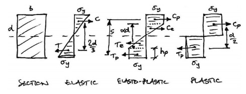
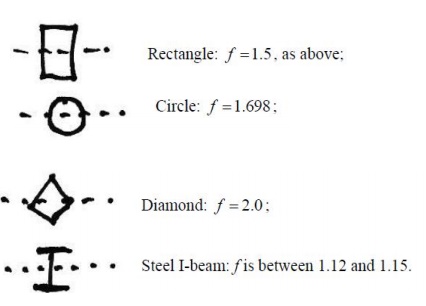
3. Shape Factor
Thus the ratio of elastic to plastic
moment capacity is:
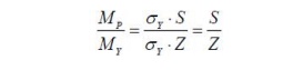
This ratio is termed the shape
factor,f, and is a property of across section alone. For a
rectangular cross-section, we have:
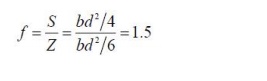
And so a rectangular section can sustain 50% more moment than the
yield moment, before a plastic hinge is formed. Therefore the shape factor is a
good measure of the efficiency of across section In bending. Shape factors for some
other cross sections are
4. Plastic Hinge
Note that once the plastic moment
capacity is reached, the section can rotate freely- that is,
it behaves like a hinge, except with moment of M patthe hinge. This is termed a
plastic hinge, and is the basis for plastic analysis. At the plastic hinge
stresses remain constant, but strains and hence rotations can increase.
4.1. Methods of Plastic Analysis
1. The Incremental
Method
This is probably the most obvious
approach: the loads on the structure are incremented until the first plastic hinge
forms. This continues until sufficient hinges have formed to collapse the
structure. This is a labour-intensive, 'brute-force', approach,
but one that is most readily suited for computer implementation.
2. The Equilibrium (or Statical) Method
In this method, free and reactant
bending moment diagrams are drawn. These diagrams are over laid to identify the
likely locations of plastic hinges. This method therefore satisfies the
equilibrium criterion first leaving the two remaining criterion to derived therefrom.
3.The Kinematic (or Mechanism) Method
In this method, a collapse
mechanism is first postulated. Virtual work equations are then written for this
collapse state, allowing the calculations of the collapse bending moment
diagram. This method satisfies the mechanism condition first, leaving the
remaining two criteria to be derived there from.
We will concentrate mainly on the
Kinematic Method, but introduce now the Incremental Method to illustrate the
main concepts.
4.1.1. Incremental Method
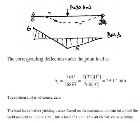
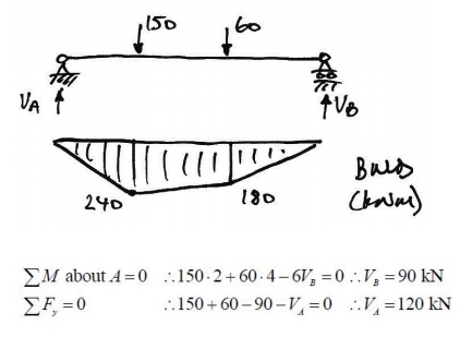
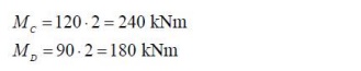
Example1- Propped Cantilever
We now assess the behavior of a simple statically
indeterminate structure under increasing load. We consider
a propped cantilever with mid-span point load:
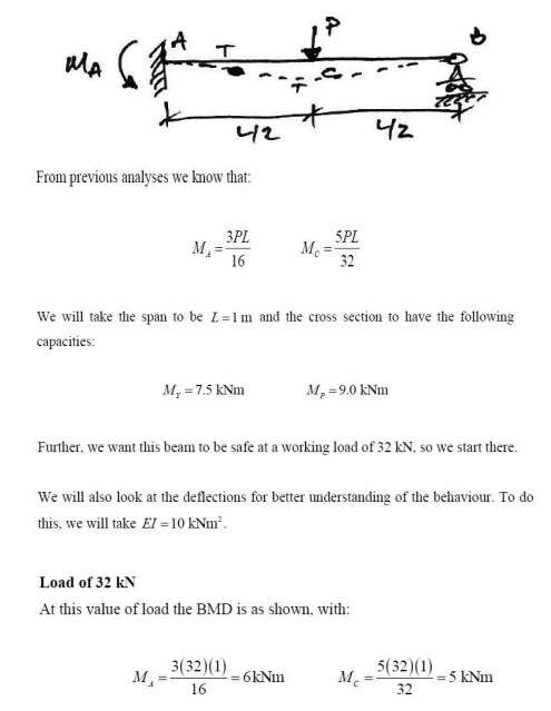
Since the peak moments are less than
the yield moments, we know that yield stress has not been reached at any point in
the beam. Also, the maximum moment occurs at A and so this point will
first reach the yield moment.
4.1.2. Equilibrium Method
Introduction
To perform this analysis we generally follow the following steps:
1.Find a primary structure by removing redundant until the structure
is statically determinate;
2.Draw the primary (or free) bending moment diagram;
3.Draw the reactant BMD for each redundant, as applied to the primary
structure;
4.Construct a composite BMD by combing
the primary and reactant BMDs;
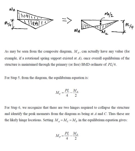
5.Determine the equilibrium equations from the composite BMD;
6.Choose the points where plastic hinges are likely to form and
introduce into the equilibrium equations;
7.Calculate the collapse load factor, or plastic moment capacity
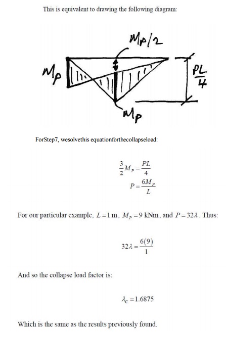
as required.
For different possible collapse mechanisms,
repeat steps 6 and 7, varying the hinge locations. We now apply this method to the
Illustrative Example previously analyzed.
Steps 1 to 3 of the Equilibrium Method
are illustrated in the following diagram:
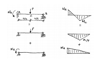
For Step 4, inconstructing the Composite
BMD, we arbitrarily choose tension on the underside of the beam as positive. By
convention in the Equilibrium Method, instead of drawing the two BMD son opposite
sides (as is actually the case), the reactant BMD is drawn 'flipped'
over
the line and subtracted from the primary BMD: the net remaining area is the final
BMD. This is best explained by illustration below:
4.1.3 Kinematic Method Using Virtual Work
Introduction
Probably the easiest way to carry
out a plastic analysis is through
the Kinematic Method using virtual work. To do this we allow the presumed shape at collapse
to be the compatible displace mentset, and the external loading and internal bending
moments to be the equilibrium set. We can then equate external and internal virtual work,
and solve for the collapse load factor for that supposed mechanism.
Remember:
Equilibrium set: the internal bending moments at collapse;
Compatibleset: the virtual collapsed configuration (see below).
Note that in the actual
collapse configuration the members
will have elastic deformation in between the plastic hinges. However, since a virtual
displacement does not have to be real, only compatible, we will choose to ignore
the elastic deformations between plastic hinges, and take the members to be straight
between them.
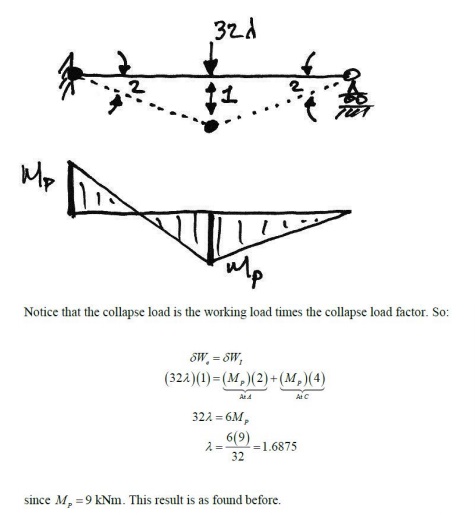
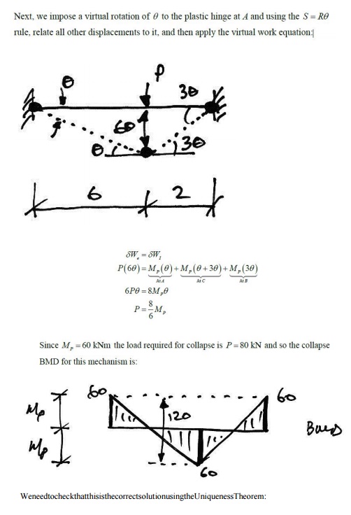
5. Collapse Mechanism
So for our previous beam, we know
that we require two hinges for collapse (one more than its degree of redundancy),
and we think that the hinges will occur under the points of peak moment, A and
C. Therefore impose a unit virtual displacement at C and relate the
corresponding virtual rotations of the hinges using,
5.1 Other Collapse Mechanisms
For the collapse mechanism looked
at previously, it seemed obvious that the plastic hinge in the span should be beneath
the load. But why? Using virtual work we can examine any possible collapse mechanism.
So let's consider
the following collapse mechanism and see why the plastic hinge has to be located
beneath the load.
Plastic Hinge between A and C:
Imposing a unit virtual deflection
at B, we get the following collapse mechanism:
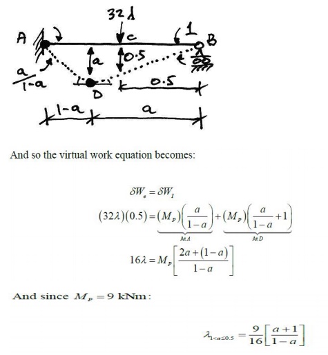
And so we see that the collapse load factor for this mechanism
depends on the position of the plastic hinge in the span.
6. Plastic Analysis of Beams
Example2-Fixed-Fixed
Beam with Point Load
To start the problem, we examine the
usual elastic BMD to see where the plastic hinges are likely to form:
We also need to know how many hinges
are required. This structure is 3? statically
indeterminate and so we might expect the number of plastic hinges required to be
4. However, since one of the indeterminacies is horizontal restraint, removing it
would not change the bending behavior of the beam.
Thus for a bending collapse only 2
indeterminacies apply and so it will only take 3 plastic hinges to cause collapse.
So looking at the elastic BMD, we'll assume
a collapse mechanism with the 3 plastic hinges at the peak moment locations: A,
B, and C.
And so the applied load is in equilibrium with the free BMD of
the collapse BMD.
2. Mechanism:
From the proposed collapse mechanism it is apparent that the beam
is a mechanism.
3. Yield:
From the collapse BMD it can be seen
that now here is exceeded. PM Thus the solution meets the three conditions and so,
by the Uniqueness Theorem, is the correct solution.
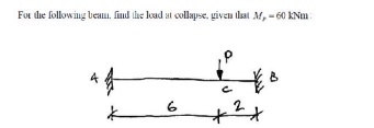
Example 3- Propped Cantilever
with Two Point Loads
For the following beam, for a load
factor of 2.0, find the required plastic moment capacity:
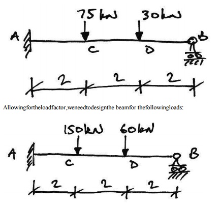
Once again we try to picture
possible failure mechanisms. Since maximum moments occur underneath point loads,
there are two real possibilities:
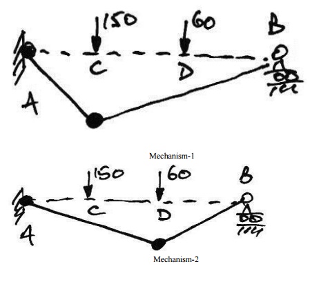
Therefore, we analyse both and
apply the Upper bound Theorem to find the design plastic moment capacity.
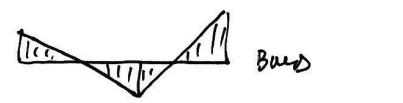
Mechanism1: Plastic Hingeat C:
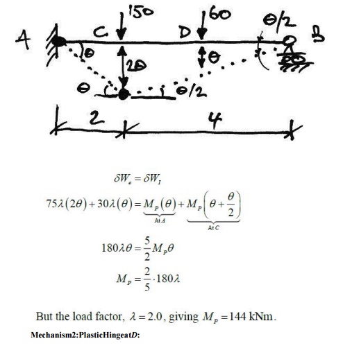
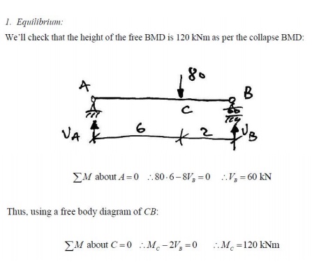
1. Equilibrium:
Using the BMD at collapse, we'll check that
the height of the free BMD is that of the equivalents imply-supported beam. Firstly
the collapse BMD from Mechanism1 is:
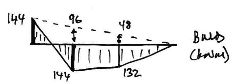
Hence, the total heights of the free
BMD are:
Checking these using a simply-supported
beam analysis
Thus, using appropriate free body
diagrams of AC and DB:

And so the applied load is in equilibrium with the free BMD of
the collapse BMD.
2. Mechanism:
From the proposed collapse mechanism
it is apparent that the beam is a mechanism. Also, since it is a propped cantilever
and thus one degree indeterminate, we require two plastic hinges for collapse, and
these we have
3.Yield:
From the collapse BMD it can be seen
that no where is the design exceeded. 144kNm Thus by the Uniqueness Theorem we have
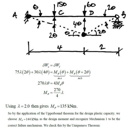
the correct solution. Lastly, we'll examine
why the Mechanism 2 collapse is not the correct solution. Since the virtual
work method provides an upper bound, then, by the Uniqueness Theorem, it must not
be the correct solution because it must violate the yield condition. Using the collapse
Mechanism 2 to determine reactions, we can draw the following BMD for collapse Mechanism
2:
From this it is apparent that Mechanism 2 is not the unique solution,
and so the design plastic moment capacity must be 144 kNmasimplied previously
from the Upper bound Theorem.
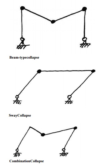
4.Basic Collapse Mechanisms:
In frames, the basic mechanisms of
collapse are:
5. Combination of Mechanisms
One of the most powerful tools in plastic analysis is
Combination of Mechanisms. This allows us to work out the virtual work equations
for the beamandsway collapses separately and then combine them to find the collapse
load factor for a combination collapse mechanism.
Combination of mechanisms is based on the idea that there are only a certain number of independent equilibrium equations for a structure. Any further equations are obtained from a combination of these independent equations. Since equilibrium equations can be obtained using
virtual work applied to a possible collapse mechanism, it follows
that there are independent collapse mechanisms, andother collapse mechanisms that
may be obtained form a combination of the independent collapse mechanisms.
6. Simple Portal Frame
In this example we will consider a basic prismatic (so all members
have the same plastic moment capacity) rectangular portal frame with pinned feet:
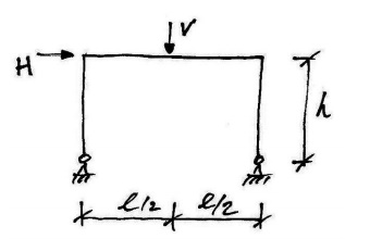
We will consider this general cases othatwecaninferthe properties and behavior of
all such frames. We will consider each of the possible mechanisms outlined above.
7.Beam collapse:
The possible beam collapse looks
as follows:
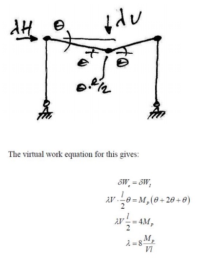
7.Collapse Mode
Since we don't know the relative values
of H and V, we cannot determine the correct collapse
mode. However, we can identify these collapse modes if we plot
the
three load factor equations derived above on the following interaction chart:
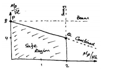
Notice that each mechanism defines
a boundary and that it is only the region inside all of these boundaries that is
safe. Now, for a given ration of V to H, we will be able to determine
the critical collapse mechanism. Note also that the beam collapse mechanism is
only critical for this frame at point P on the chart- this point
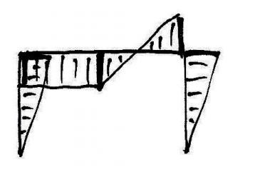
is also included in the Combined mechanism. The bending moment diagrams corresponding
to each of the mechanisms are approximately:
An interesting phenomenon is observed
at point Q on the chart, where the Sway and Combined mechanisms give the
same result. Looking at the bending moment diagrams, we can see that this
occurs as the moment at the top of the left column becomes equal to the
mid-span moment of the beam:
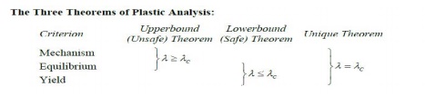
8. Upper bound (Unsafe) Theorem:
This can be stated as:
If a bending moment diagram is found
which satisfies the conditions of equilibrium and mechanism (but not necessarily
yield), then the corresponding load factor is either greater than or equal to
the true load factor at collapse.
This is called the unsafe theorem
because for an arbitrarily assumed mechanism the load factor is either exactly
right (when the yield criterionismet) or is wrong and is too large, leading a
designer to think that the frame can carry more load than is actually possible.
9. Lower bound (Safe)Theorem:
If a bending moment diagram is found
which satisfies the conditions of equilibrium and yield (but not necessarily that
of mechanism), then the corresponding load factor is either less than or equal to
the true load factor at collapse
Related Topics