Chapter: Compilers : Principles, Techniques, & Tools : Code Generation
Optimal Code Generation for Expressions
Optimal Code Generation for
Expressions
1 Ershov
Numbers
2
Generating Code From Labeled Expression Trees
3
Evaluating Expressions with an Insufficient Supply of Reg-isters
4
Exercises for Section 8.10
We can choose registers optimally when a basic
block consists of a single expres-sion evaluation, or if we accept that it is
sufficient to generate code for a block one expression at a time. In the
following algorithm, we introduce a numbering scheme for the nodes of an
expression tree (a syntax tree for an expression) that allows us to generate
optimal code for an expression tree when there is a fixed number of registers
with which to evaluate the expression.
1. Ershov Numbers
We begin by assigning to the nodes of an expression
tree a number that tells how many registers are needed to evaluate that node
without storing any tem-poraries. These numbers are sometimes called Ershov numbers, after A. Ershov, who
used a similar scheme for machines with a single arithmetic register. For our
machine model, the rules are:
1. Label
any leaf 1.
2. The
label of an interior node with one child is the label of its child.
3. The
label of an interior node with two children is
(a) The larger of the labels of its children, if
those labels are different.
(b) One plus the label of its children if the
labels are the same.
E x a m p l e 8.23 : In Fig. 8.23 we see an
expression tree (with operators omitted) that might be the tree for expression (a —
b) + e x (c + d) or the three-address code:
t l = a
- b
t 2 = c
+ d
t 3 = e
* t 2
t 4 = t l
+ t 3
Each of the five leaves is labeled 1 by rule (1).
Then, we can label the interior node for tl = a - b , since both of its
children are labeled. Rule (3b) applies, so it gets label one more than the
labels of its children, that is, 2. The same holds for the interior node for t2
= c + d.
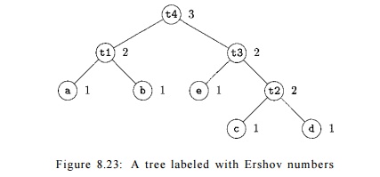
Now, we can work on the node for
t3 = e * t 2 . Its children have labels 1 and 2, so the label of the node for t3
is the maximum, 2, by rule (3a). Finally, the root, the
node for t4 = tl + t 3 , has two
children with label 2, and therefore it gets
label 3.
2. Generating Code From Labeled
Expression Trees
It can be proved that, in our machine model, where
all operands must be in registers, and registers can be used by both an operand
and the result of an operation, the label of a node is the fewest registers
with which the expression can be evaluated using no stores of temporary
results. Since in this model, we are forced to load each operand, and we are
forced to compute the result cor-responding to each interior node, the only
thing that can make the generated code inferior to the optimal code is if there
are unnecessary stores of tempo-raries. The argument for this claim is embedded
in the following algorithm for generating code with no stores of temporaries,
using a number of registers equal to the label of the root.
Algorithm 8 . 2 4 : Generating code from a labeled
expression tree.
INPUT : A labeled tree with each operand appearing once (that is, no common subexpressions).
OUTPUT : An optimal sequence of machine instructions to evaluate the root
into a register.
METHOD : The following is a recursive
algorithm to generate the machine code. The
steps below are applied, starting at the root of the tree. If the algorithm is
applied to a node with label k, then
only k registers will be used.
However, there is a "base" 6
> 1 for the registers used so that the actual registers used are Rb,Rb+i,- --Rb+k-i- The result always
appears in Rb+k-i-
To generate machine code for an
interior node with label k and two
chil-dren with equal labels (which must be k
— 1) do the following:
Recursively generate code for the
right child, using base 6 + 1. The
result of the right child appears in register Rb+k •
Recursively generate code for the
left child, using base 6; the result
appears in Rb+k-i-
Generate the instruction OP Rb+k,Rb+k-i,Rb+k, where OP is the
appropriate operation for the interior node in question.
Suppose we have an interior node
with label k and children with
unequal
labels. Then one of the children, which we'll call
the "big" child, has label k, and the other child, the "little" child, has some label
m < k. Do the following to generate code for this interior node, using base 6:
Recursively generate code for the
big child, using base b; the result appears in register Rb+k-i-
Recursively generate code for the
small child, using base 6; the result appears
in register Rb+m-1. Note
that since m < k, neither
Rb+k-i nor any higher-numbered
register is used.
(c) Generate the instruction OP Rb+k-i, Rb+m-i, Rb+k-i or
the instruction OP Rb+k-i, Rb+k-i, Rb+m-i5 depending on whether the big child is the right or left child,
respectively.
For a leaf representing operand
x, if the base is 6 generate the instruction LD Rb, x.
Example 8 . 2 5 :
Let us apply
Algorithm 8.24 to the tree
of Fig.
8.23. Since the label of the
root is 3, the
result will appear in R3, and
only Ry, R2,
and R3 will be used. The base for the root is b = 1. Since the root has
children of equal labels, we generate code for the right child first, with base
2.
When we generate code for the
right child of the root, labeled t3,
we find the big child is the right child and the little child is the left
child. We thus generate code for the right child first, with 6 = 2. Applying the rules for
equal-labeled children and leaves, we generate the following code for the node
labeled ii:
LD R3, D
LD R2, C
ADD R3, R2, R3
Next, we generate code for the
left child of the right child of the root; this node is the leaf labeled e.
Since b — 2, the proper instruction
is
LD R2, e
Now we can complete the code for
the right child of the root by adding the instruction
MUL
R3, R2, R3
The algorithm proceeds to
generate code for the left child of the root, leaving the result in R2, and with base 1. The complete sequence of instructions is shown in Fig. 8.24.
LD R3,
d
LD R2,
c
ADD R3, R2, R3
LD R2,
e
MUL R3, R2, R3
LD R2,
b
LD Rl,
a
SUB R2, Rl, R2
ADD R3, R2, R3
Figure 8.24: Optimal
three-register code for the tree of Fig. 8.23
3. Evaluating Expressions with an Insufficient Supply of Registers
When there are fewer registers available than the label of the root of
the tree, we cannot apply Algorithm 8.24 directly. We need to introduce some store instructions that spill
values of subtrees into memory, and we then need to load those values back into
registers as needed. Here is the modified algorithm that takes into account a
limitation on the number of registers.
Algorithm 8 . 2 6 :
Generating code from a labeled expression tree.
INPUT : A labeled tree with each operand appearing once (i.e., no common subexpressions) and a number of registers
r > 2.
OUTPUT : An optimal sequence of machine
instructions to evaluate the root into a
register, using no more than r registers, which we assume are Ri, R2, •.. ,Rr-
METHOD : Apply the following recursive algorithm, starting at the root of the tree, with base 6 = 1. For a node JV
with label r or less, the algorithm
is exactly the same as Algorithm 8.24, and we shall not repeat those steps here. However, for interior nodes
with a label k > r, we need to
work on each side of the tree separately and store the result of the larger
subtree. That result is brought back into memory just before node iV is
evaluated, and the final step will take place in registers Rr-1 and Rr- The modifications to the basic algorithm are as follows:
1. Node N has at least one child with label r or greater. Pick the larger child (or either if their labels are
the same) to be the "big" child and let the other child be the
"little" child.
2. Recursively generate code for the big child, using base 6 = 1. The
result of this evaluation will appear in register Rr.
3. Generate the machine instruction ST tk,Rr, Where is a temporary
variable used for temporary results used to help evaluate nodes with label k.
4. Generate code for the little child as follows. If the little child has label r or greater,
pick base 6 = 1 . If the label of the little child is j < r, then pick 6 = r
— j. Then recursively apply this
algorithm to the little child; the
result appears in Rr.
5. Generate the instruction LD
Rr^i,tk-
6. If the big child is the right child
of N, then generate the
instruction OP Rr, Rr, Rr-1. If the big child is the left child, generate OP
Rr, Rr-i, Rr-
E x a m p l e 8 . 2 7 : Let us revisit the
expression represented by Fig. 8.23, but now assume that r = 2; that is, only registers Rl and R2 are available to hold tem-poraries used in the evaluation of
expressions. When we apply Algorithm 8.26 to Fig.
8.23, we see that the root, with label 3, has a
label that is larger than r = 2. Thus, we need to identify one of the children as the "big"
child. Since they have equal labels, either would do. Suppose we pick the right
child as the big child.
Since the label of the big child of the root is 2, there
are enough registers. We thus apply Algorithm 8.24 to this
subtree, with 6 = 1 and two registers. The result looks very much like the code
we generated in Fig. 8.24, but with registers Rl and R2 in place of R2 and R3. This code is
LD R2, d
LD Rl, c
ADD R2, Rl, R2
LD Rl, e
MUL R2, Rl, R2
Now, since we need both registers
for the left child of the root, we need to generate the instruction
ST t3, R2
Next, the left child of the root is handled. Again, the number of
registers is sufficient for this child, and the code is
LD R2, b
LD Rl, a
SUB R2, Rl, R2
Finally, we reload the temporary that holds the right child of the root
with the instruction
LD Rl, t3
and execute the operation at the root of the tree with the instruction
ADD R2, R2, Rl
The complete sequence of instructions is shown in Fig. 8.25.
LD R2 d
LD Rl c
ADD R2 Rl, R2
LD Rl e
MUL R2 Rl, R2
ST t3 R2
LD R2 b
LD Rl a
SUB R2 Rl, R2
LD Rl t3
ADD R2 R2, Rl
Figure 8.25: Optimal three-register code for the tree of Fig. 8.23, using
only two registers
4. Exercises
for Section 8.10
Exercise 8 . 1 0 .
1 : Compute Ershov numbers for the
following expressions:
a) a/(b + c) - d* (e + / ) .
b) a + b * (c * (d + e)).
(—a +
*p)*((b-*q)/(—c+*r)).
Exercise 8 . 1 0 . 2: Generate optimal code using two registers for each of the
expressions of Exercise 8.10.1.
Exercise 8 . 1 0 . 3: Generate optimal code using three registers for each of the
expressions of Exercise 8.10.1.
!
Exercise 8. 1 0.4: Generalize the computation of Ershov numbers to expression trees
with interior nodes with three or more children.
!
Exercise 8.10.5:
An assignment to an array element, such as a [ i ]
= x, ap-pears to be an operator with three operands: a, i, and x. How would
you modify the tree-labeling scheme to generate optimal code for this machine
model?
Exercise 8 . 1 0 . 6 : The
original Ershov numbers were used for a machine that allowed
the right operand of an expression to be in memory, rather than a register. How
would you modify the tree-labeling scheme to generate optimal code for this
machine model?
Exercise 8 . 1 0 . 7: Some
machines require two registers for certain single-pre-cision values. Suppose
that the result of a multiplication of single-register quan-tities requires two
consecutive registers, and when we divide a/6, the
value of a must be held in two
consecutive registers. How would you modify the tree-labeling scheme to
generate optimal code for this machine model?
Related Topics