Chapter: Digital Electronics : Sequential Circuits
Master-Slave Flip-Flops
MASTER-SLAVE FLIP-FLOPS:
A pulse-triggered SR flip-flop is a level-clocked flip-flop; however, for any change in output to occur, both the high and low levels of the clock must rise and fall. Pulse-triggered flip-flops are also called master-slave flip-flop; the master accepts the initial inputs and the “whips” the slave with its output when the negative clock edge arrives. Another analogy often used is to say that during the positive edge, the master gets cocked (like a gun), and during the negative clock edge, the slave gets triggered.The master is simply a clocked SR
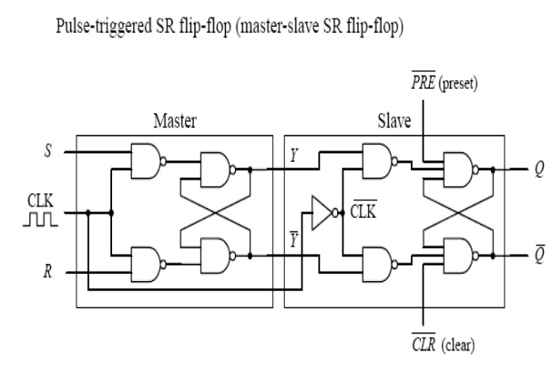
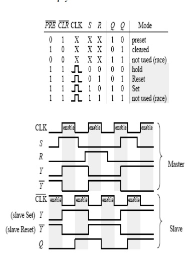
flip-flop that is enabled during the high clock pulse and outputs Y and Y_ (either set, reset, or no change). The slave is similar to the master, but it gets enabled only during the negative clock pulse (due to the inverter). The moment the slave is enabled, it uses the Y and Y’ outputs of the master as inputs and then outputs the final result. Notice the preset (P_R_E_) and clear (C_L_R_) inputs. These are called asynchronous inputs. Unlike the synchronous inputs, S and R, the asynchronous input disregard the clock and either clear (also called asynchronous reset) or preset (also called asynchronous set) the flip-flop. When C_L_R_ is high and P_R_E_ is low, you get asynchronous reset, Q = 1, Q’ = 0, regardless of the CLK, S, and R inputs. These active-low inputs are therefore normally pulled high to make them inactive. As you will see later when I discuss flip-flop applications, the ability to apply asynchronous set and resets is often used to clear entire registers that consist of an array of flip-flops.
1. Level-Triggered SR Flip-Flop:
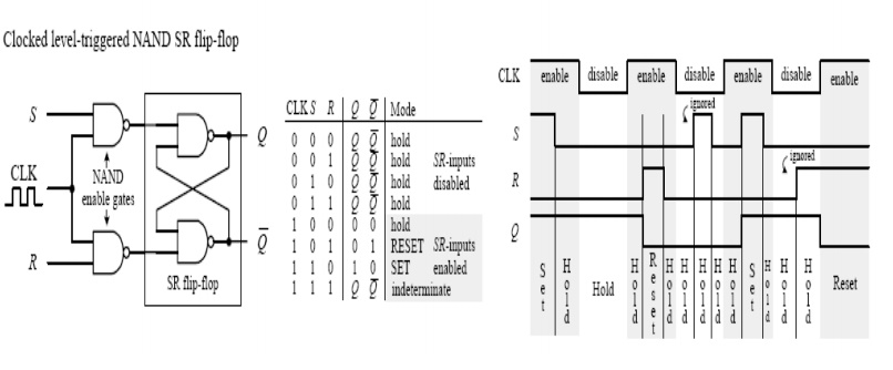
Now it would be nice to make an SR flip-flop synchronous—meaning making the S and R inputs either enabled or disabled by a control pulse, such as a clock. Only when the clock pulse arrives are the inputs sampled. Flip-flops that respond in this manner are referred to as synchronous or clocked flip-flops (as opposed to the preceding asynchronous flip-flops). To make the preceding SR flip-flop into a synchronous or clocked device, simply attach enable gates to the inputs of the flip-flop, as shown in Fig.(Here, the cross-NAND arrangement is used, though a cross-NOR arrangement also can be used.) Only when the clock is high are the S and R inputs enabled. When the clock is low, the inputs are disabled, and the flip-flop is placed in hold mode. The truth table and timing diagram below help illustrate how this device works.
2. Ripple Counter (Asynchronous Counter) :
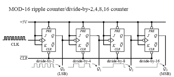
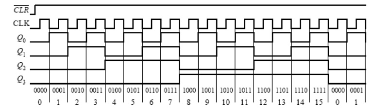
Asimple counter, called a MOD-16 ripple counter (or asynchronous counter), can be constructed by joining four JK flop-flops together, as shown in Fig. (MOD-16, or modulus 16, means that the counter has 16 binary states.) This means that it can count from 0 to 15— the zero is one of the counts. Each flip-flop in the ripple counter is fixed in toggle mode (J and K are both held high). The clock signal applied to the first flip-flop causes the flip-flop to divide the clock signal’s frequency by 2 at its Q0 output—a result of the toggle. The second flip-flop receives Q0’s output at its clock input and likewise divides by 2. The process continues down the line. What you get in the end is a binary counter with four digits. The least significant bit (LSB) is Q0, while the most significant bit (MSB) is Q4. When the count reaches 1111, the counter recycles back to 0000 and continues from there. To reset the counter at any given time, the active-low clear line is pulsed low.To make the counter count backward from 1111 to 0000, you would simply use theQ’ outputs.
The ripple counter above also can be used as a divide-by-2,4,8,16 counter. Here, you simply replace the clock signal with any desired input signal that you wish to divide in frequency. To get a divide-by-2 counter, you only need the first flip-flop; to get a divide-by-8 counter, you need the first three flip-flops. Ripple counters with higher MOD values can be constructed by slapping on more flip-flops to the MOD-16 counter. But how do you create a ripple counter with a MOD value other than 2, 4, 8, 16, etc.? For example, say you want to create a MOD-10 (0 to 9) ripple counter. Likewise, what do you do if you want to stop the counter after a particular count has been reached and then trigger some device, such as an LED or buzzer. The figure below shows just such a circuit.
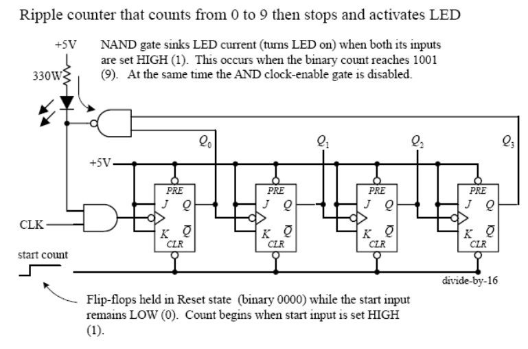
To make a MOD-10 counter, you simply start with the MOD-16 counter and connect the Q0 and Q3 outputs to a NAND gate, as shown in the figure.When the counter reaches 9 (1001), Q0 and Q3 will both go high, causing the NAND gate’s output to go low. The NAND gate then sinks current, turning the LED on, while at the same time disabling the clock-enable gate and stopping the count. (When the NAND gate is high, there is no potential difference across the LED to light it up.) To start a new count, the active-low clear line is momentarily pulsed low. Now, to make a MOD-15 counter, you would apply the same basic approach used to the left, but you would connect Q1,Q2, and Q3 to a three-input NAND gate.
Related Topics