Chapter: Computer Networks : Network Layer
Logical Addressing - IPv4 Addresses
Logical Addressing - IPv4
Addresses
An IPv4
address is a 32-bit address that uniquely and universally defines the
connection of a device (for example, a computer or a router) to the Internet.
IPv4 addresses are unique. They are unique in the sense that each address
defines one, and only one, connection to the Internet. Two devices on the
Internet can never have the same address at the same time. The IPv4 addresses
are universal in the sense that the addressing system must be accepted by any
host that wants to be connected to the Internet.
1. Address Space
A
protocol such as IPv4 that defines addresses has an address space. An address
space is the total number of addresses used by the protocol. If a protocol uses
N bits to define an address, the
address space is 2N because each bit
can have two different values (0 or 1) and N
bits can have 2N values.
IPv4 uses
32-bit addresses, which means that the address space is 232 or 4,294,967,296 (more
than 4 billion). This means that, theoretically, if there were no restrictions,
more than 4 billion devices could be connected to the Internet.
2. Notations
There are
two prevalent notations to show an IPv4 address: binary notation and dotted
decimal notation.
a. Binary Notation
In binary
notation, the IPv4 address is displayed as 32 bits. Each octet is often
referred to as a byte. So it is common to hear an IPv4 address referred to as a
32-bit address or a 4-byte address. The following is an example of an IPv4
address in binary notation.
01110101
10010101 00011101 00000010
b. Dotted-Decimal Notation
To make
the IPv4 address more compact and easier to read, Internet addresses are
usually written in decimal form with a decimal point (dot) separating the
bytes. The following is the dotted-decimal notation of the above address:
117.149.29.2
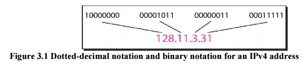
Figure
3.1 shows an IPv4 address in both binary and dotted-decimal notation. Note that
because each byte (octet) is 8 bits, each number in dotted-decimal notation is
a value ranging from 0 to 255
Example 3.1
Change
the following IPv4 addresses from binary notation to dotted-decimal notation.
a)10000001
00001011 00001011 11101111
b)11000001
10000011 00011011 11111111
Solution
We
replace each group of 8 bits with its equivalent decimal number and add dots
for separation.
a)129.11.11.239
b)193.131.27.255
Example 3.2
Change
the following IPv4 addresses from dotted-decimal notation to binary notation.
a)111.56.45.78
b)221.34.7.82
Solution
We
replace each decimal number with its binary equivalent.
a)01101111
00111000 00101101 01001110
b)11011101
00100010 00000111 01010010
Example 3.3
Find the
error, if any, in the following IPv4 addresses.
a)111.56.045.78
b)221.34.7.8.20
c) 75.45.301.14
d)11100010.23.14.67
Solution
a)There
must be no leading zero (045).
b)There can
be no more than four numbers in an IPv4 address.
c) Each
number needs to be less than or equal to 255 (301 is outside this range).
d)A mixture
of binary notation and dotted-decimal notation is not allowed.
3. Classful Addressing
IPv4
addressing, at its inception, used the concept of classes. This architecture is
called classful addressing. In classful addressing, the address space is
divided into five classes: A, B, C, D, and E.
We can
find the class of an address when given the address in binary notation or
dotted-decimal notation. If the address is given in binary notation, the first
few bits can immediately tell us the class of the address. If the address is
given in decimal-dotted notation, the first byte defines the class. Both
methods are shown in Figure 3.2.
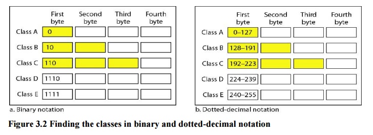
Example 3.4
Find the
class of each address.
a)00000001
00001011 00001011 11101111
b)11000001
10000011 00011011 11111111
c) 14.23.120.8
d)252.5.15.111
Solution
a)The first
bit is O. This is a class A address.
b)The first
2 bits are 1; the third bit is O. This is a class C address.
c) The first
byte is 14 (between 0 and 127); the class is A.
d)The first
byte is 252 (between 240 and 255); the class is E.
3.1 Classes and Blocks
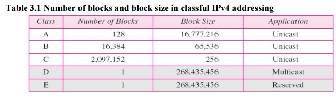
One
problem with classful addressing is that each class is divided into a fixed
number of blocks with each block having a fixed size as shown in Table 3.1.
Class A
addresses were designed for large organizations with a large number of attached
hosts or routers. Class B addresses was designed for midsize organizations with
tens of thousands of attached hosts or routers. Class C addresses were designed
for small organizations with a small number of attached hosts or routers. Class
D addresses were designed for multicasting. The class E addresses were reserved
for future use. In c1assfnl addressing, a large part of the available addresses
were wasted
3.2 Netid and Hostid
In
classful addressing, an IP address in class A, B, or C is divided into netid
and hostid.
These
parts are of varying lengths, depending on the class of the address. The netid
is in color, the hostid is in white. Note that the concept does not apply to
classes D and E. In class A, one byte defines the netid and three bytes define
the hostid. In class B, two bytes define the netid and two bytes define the
hostid. In class C, three bytes define the netid and one byte defines the
hostid.
3.3 Mask
Although the
length of the
netid and hostid
(in bits) is
predetermined in classful addressing, we can also use a mask
(also called the default mask), a 32-bit number made of contiguous Is followed
by contiguous as. The masks for classes A, B, and C are shown in Table 3.2. The
concept does not apply to classes D and E
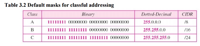
The mask
can help us to find the netid and the hostid. For example, the mask for a class
A address has eight 1s, which means the first 8 bits of any address in class A
define the netid; the next 24 bits define the hostid. The last column of Table
3.2 shows the mask in the form /n
where n can be 8, 16, or 24 in
classful addressing. This notation is also called slash notation orClassless
Interdomain Routing (CIDR) notation. The notation is used in classless
addressing,
3.4 Subnetting
If an
organization was granted a large block in class A or B, it could divide the
addresses
into
several contiguous groups and assign each group to smaller networks (called
subnets). Subnetting increases the number of Is in the mask.
3.5 Supernetting
In
supernetting, an organization can combine several class C blocks to create a
larger range of addresses. In other words, several networks are combined to
create a supernetwork or a supemet. An organization can apply for a set of
class C blocks instead of just one.
3.6 Address Depletion
The flaws
in classful addressing scheme combined with the fast growth of the Internet led
to the near depletion of the available addresses. Yet the number of devices on
the Internet is much less than the 232 address space. We have run out of class
A and B addresses, and a class C block is too small for most midsize
organizations. One solution that has alleviated the problem is the idea of
classless addressing.
4. Classless Addressing
To
overcome address depletion and give more organizations access to the Internet,
classless addressing was designed and implemented. In this scheme, there are no
classes, but the addresses are still granted in blocks.
4.1 Address Blocks
In
classless addressing, when an entity, small or large, needs to be connected to
the Internet, it is granted a block (range) of addresses. The size of the block
varies based on the nature and size of the entity. For example, a household may
be given only two addresses; a large organization may be given thousands of
addresses. An ISP, as the Internet service provider, may be given thousands or
hundreds of thousands based on the number of customers it may serve.
Restrictions
to simplify the handling of addresses, the Internet authorities impose three
restrictions on classless address blocks:
1. The
addresses in a block must be contiguous, one after another.
2. The
number of addresses in a block must be a power of 2 (I, 2, 4, 8 ...).
3. The first
address must be evenly divisible by the number of addresses.
Example 3.5
Figure
3.3 shows a block of addresses, in both binary and dotted-decimal notation,
granted to a small business that needs 16 addresses.
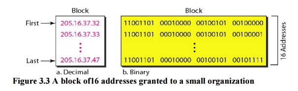
We can
see that the restrictions are applied to this block. The addresses are
contiguous. The number of addresses is a power of 2 (16 = 24), and the first
address is divisible by 16. The first address, when converted to a decimal
number, is 3,440,387,360, which when divided by 16 results in 215,024,210.
4.2 Mask
A better
way to define a block of addresses is to select any address in the block and
the mask. As we discussed before, a mask is a 32-bit number in which the n
leftmost bits are 1s and the 32 - n rightmost bits are 0s. However, in
classless addressing the mask for a block can take any value from 0 to 32. It
is very convenient to give just the value of n preceded by a slash.
First Address: The first address in the block
can be found by setting the 32 - n rightmost bits inthe binary notation of the
address to 0s. The first address in the block can be found by setting the
rightmost 32 - n bits to 0s.
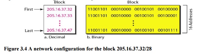
Example 3.6
A block
of addresses is granted to a small organization. We know that one of the
addresses is 205.16.37.39/28. What is the first address in the block?
Solution
The
binary representation of the given address is 11001101 00010000 00100101 00100
I 11. If we set 32 - 28 rightmost bits to 0, we get 11001101 000100000100101
0010000 or 205.16.37.32.
Last Address: The last address in the block
can be found by setting the 32 - n rightmost bits inthe binary notation of the
address to Is. The last address in the block can be found by setting the
rightmost 32 - n bits to Is.
Example 3.7
Find the
last address for the block in Example 3.6.
Solution
The
binary representation of the given address is 11001101
000100000010010100100111. If we set 32 - 28 rightmost bits to 1, we get
11001101 00010000 001001010010 1111 or 205.16.37.47.
Number of Addresses: The
number of addresses in the block is the difference between the lastand first
address. It can easily be found using the formula 232- n.
Example 3.8
Find the
number of addresses in Example 3.6.
Solution
The value
of n is 28, which means that number of addresses is 232- 28 or 16.
Example 3.9
Another
way to find the first address, the last address, and the number of addresses is
to represent the mask as a 32-bit binary (or 8-digit hexadecimal) number. This
is particularly useful when we are writing a program to find these pieces of
information. In Example 19.5 the /28 can be represented as 11111111 11111111
11111111 11110000 (twenty-eight 1s and four 0s).
Find
a. The
first address
b. The
last address
c. The
number of addresses
Solution
a. The
first address can be found by ANDing the given addresses with the mask. ANDing
here is done bit by bit. The result of ANDing 2 bits is 1 if both bits are Is;
the result is 0 otherwise.
Address:
11001101 00010000 00100101 00100111
Mask:
11111111 11111111 11111111 11110000
First
address: 11001101 00010000 00100101 00100000
b. The
last address can be found by ORing the given addresses with the complement of
the mask. ORing here is done bit by bit. The result of ORing 2 bits is 0 if
both bits are 0s; the result is 1 otherwise. The complement of a number is
found by changing each 1 to 0 and each 0 to 1.
Address:
11001101 00010000 00100101 00100111
Mask
complement: 00000000 00000000 00000000 00001111
Last
address: 11001101 00010000 00100101 00101111
c. The
number of addresses can be found by complementing the mask, interpreting it as
a decimal number, and adding 1 to it.
Mask
complement: 000000000 00000000 00000000 00001111
Number of
addresses: 15 + 1 =16
4.3 Network Addresses
A very
important concept in IP addressing is the network address. When an organization
is given
a block of addresses, the organization is free to allocate the addresses to the
devices that need to be connected to the Internet. The first address in the
class, however, is normally (not always) treated as a special address. The
first address is called the network address and defines the organization
network. It defines the organization itself to the rest of the world.
The
organization network is connected to the Internet via a router. The router has
two addresses. One belongs to the granted block; the other belongs to the
network that is at the other side of the router. We call the second address
x.y.z.t/n because we do not know anything about the network it is connected to
at the other side. All messages destined for addresses in the organization
block (205.16.37.32 to 205.16.37.47) are sent, directly or indirectly, to
x.y.z.t/n. We say directly or indirectly because we do not know the structure of
the network to which the other side of the router is connected. The first
address in a block is normally not assigned to any device; it is used as the
network address that represents the organization to the rest of the world.
4.4 Hierarchy
IP
addresses, like other addresses or identifiers we encounter these days, have
levels of hierarchy. For example, a telephone network in North America has
three levels of hierarchy. The leftmost three digits define the area code, the
next three digits define the exchange, the last four digits define the
connection of the local loop to the central office. Figure 3.5 shows the
structure of a hierarchical telephone number

Two-Level Hierarchy: No Subnetting
An IP
address can define only two levels of hierarchy when not subnetted. The n
leftmost bits of the address x.y.z.tJn define the network (organization
network); the 32 – n rightmost bits define the particular host (computer or
router) to the network. The two common terms are prefix and suffix. The part of
the address that defines the network is called the prefix; the part that
defines the host is called the suffix. Figure 3.6 shows the hierarchical
structure of an IPv4 address.
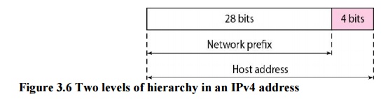
The
prefix is common to all addresses in the network; the suffix changes from one
device to another. Each address in the block can be considered as a two-level
hierarchical structure: the leftmost n bits (prefix) define the network; the
rightmost 32 - n bits define the host.
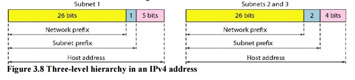
Note that
applying the mask of the network, /26 to any of the addresses gives us the
network address 17.12.14.0/26. We leave this proof to the reader. We can say
that through subnetting, we have three levels of hierarchy. Note that in our
example, the subnet prefix length can differ for the subnets as shown in Figure
3.8.
More Levels of Hierarchy
The
structure of classless addressing does not restrict the number of hierarchical
levels. An organization can divide the granted block of addresses into
subblocks. Each subblock can in turn be divided into smaller subblocks. And so
on. One example of this is seen in the ISPs. A national ISP can divide a
granted large block into smaller blocks and assign each of them to a regional
ISP. A regional ISP can divide the block received from the national ISP into
smaller blocks and assign each one to a local ISP. A local ISP can divide the
block received from the
regional
ISP into smaller blocks and assign each one to a different organization.
Finally, an organization can divide the received block and make several subnets
out of it.
5. Address Allocation
The next
issue in classless addressing is address allocation. The ultimate
responsibility of address allocation is given to a global authority called the
Internet Corporation for Assigned Names and Addresses (ICANN). However, ICANN
does not normally allocate addresses to individual organizations. It assigns a
large block of addresses to an ISP. Each ISP, in turn, divides its assigned
block into smaller subblocks and grants the subblocks to its customers. In
other words, an ISP receives one large block to be distributed to its Internet
users. This is called address aggregation: many blocks of addresses are
aggregated in one block and granted to one ISP.
Example 3.10
An ISP is
granted a block of addresses starting with 190.100.0.0/16 (65,536 addresses).
The ISP needs to distribute these addresses to three groups of customers as
follows:
a)
The first group has 64 customers; each needs 256
addresses.
b) The
second group has 128 customers; each needs 128 addresses.
c)
The third group has 128 customers; each needs 64
addresses.
Design
the subblocks and find out how many addresses are still available after these
allocations.
Solution
Figure 3.9 shows the situation.
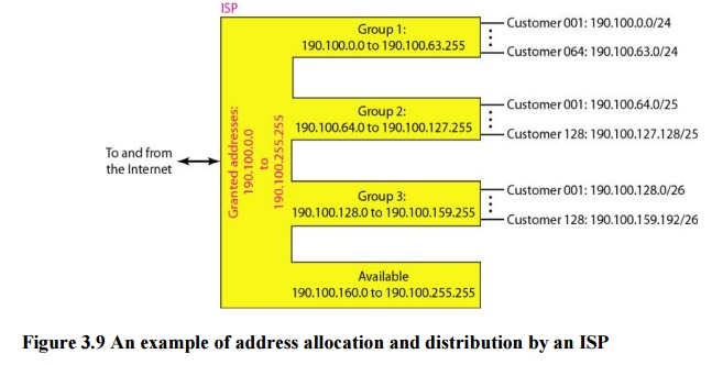
1. Group
1
For this
group, each customer needs 256 addresses. This means that 8 (log2256) bits are
needed to define each host. The prefix length is then 32 - 8 =24. The addresses
are
1st
Customer: 190.100.0.0/24 100.0.255/24
2nd
Customer: 190.100.1.0/24190 190.100.1.255/24
64th
Customer: 190.100.63.0/24 190.100.63.255/24
Total =64
X 256 =16,384
2. Group2
For this
group, each customer needs 128 addresses. This means that 7 (10g2 128) bits are
needed to define each host. The prefix length is then 32 - 7 =25. The addresses
are
3. Group3
For this
group, each customer needs 64 addresses. This means that 6 (log2 64) bits are
needed to each host. The prefix length is then 32 - 6 =26. The addresses are
1st
Customer: 190.100.128.0/26 190.100.128.63/26
2nd
Customer: 190.100.128.64/26 190.100.128.127/26
128th
Customer: 190.100.159.192/26 190.100.159.255/26
Total =128
X 64 =8192
Number of
granted addresses to the ISP: 65,536
Number of
allocated addresses by the ISP: 40,960
Number of
available addresses: 24,576
Related Topics