Chapter: Mechanical : Dynamics of Machines : Force Analysis
Inertia Forces in a Reciprocating Engine, Considering the Weight of connecting Rod
INERTIA FORCES IN A RECIPROCATING
ENGINE, CONSIDERING THE WEIGHT OF CONNECTING ROD
In a
reciprocating engine, let OC be the
crank and PC, the connecting rod
whose centre of gravity lies at G.
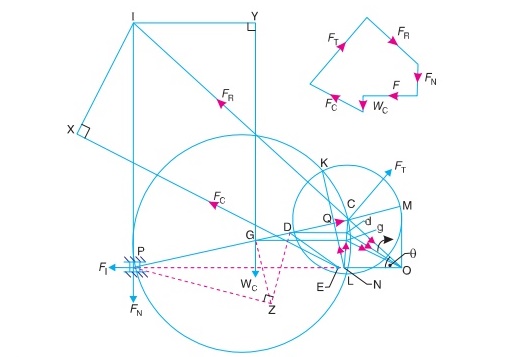
The inertia forces in a reciprocating engine may be obtained graphically as
discussed below:
1. First
of all, draw the acceleration diagram OCQN
by KlienÔÇÖs construction. We know
that the acceleration of the piston P
with respect to O,
acting in the direction from N to O.
Therefore, the inertia force FI
of the reciprocating parts will act in the opposite direction as shown in Fig.
15.22.
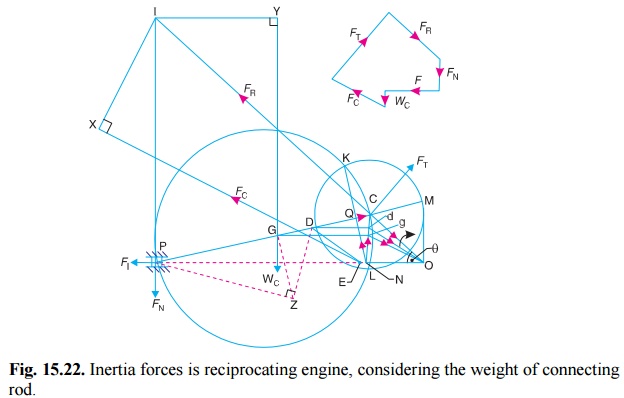
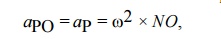
Fig. 15.22. Inertia forces is reciprocating
engine, considering the weight of connecting rod.
2. Replace
the connecting rod by dynamically equivalent system of two masses as discussed
in Art. 15.12. Let one of the masses be arbitrarily placed at P. To obtain the position of the other
mass, draw GZ perpendicular to CP such that GZ = k, the radius of
gyration of the connecting rod. Join PZ
and from Z draw perpendicular to DZ which intersects CP at D. Now, D is the position of the second mass.
Note: The position of the second mass may
also be obtained from the equation,
GP
├Ś
GD = k2
3. Locate the points G and D on NC which is the
acceleration image of the connecting
rod. This is done by drawing parallel lines from G and D to the line of
stroke PO. Let these parallel lines
intersect NC at g and d respectively.
Join gO and dO. Therefore, acceleration
of G with respect to O, in the direction from g to O,
aGO = aG = ¤ë2 ├Ś gO
and acceleration of D with respect to O, in the direction from d
to O,
aDO =
aD = ¤ë2 ├Ś dO
From D, draw DE parallel to dO which intersects the line of stroke PO at E. Since the accelerating forces on the masses at P and D intersect at E, therefore
their resultant must also pass through E.
But their resultant is equal to the accelerang force on the rod, so that the
line of action of the accelerating force on the rod, is given by a line drawn
through E and parallel to gO, in the direc- tion from g to O.
The inertia force of the connecting rod FC therefore acts through E and in the opposite direction as
shown in Fig. 15.22. The inertia
force of the connecting rod is given by

A little consideration will show that the forces acting on the connecting rod are :
(a) Inertia force of the reciprocating
parts (FI ) acting along
the line of stroke PO,
(b) The side thrust between the
crosshead and the guide bars (FN)
acting at P and
right angles to line of stroke PO,
(c) The weight of the
connecting rod
(W
C = mC.g), (d) Inertia force of the connecting
rod (FC),
(e) The radial force (FR)
acting through O and parallel to the
crank OC, (f) The force (FT)
acting perpen- dicular to the crank OC.
Now, produce the lines of action of FR and FN to intersect at a point I, known as instantaneous centre. From I draw I X and I Y , perpendicular to the lines of
action of FC and W C. Taking moments about I, we have
FT ├Ś IC = FI ├Ś IP + FC ├Ś I X + W C ├Ś I Y ...(ii)
The value of FT may be obtained from this equation and from the force
polygon as
shown in Fig. 15.22, the forces FN and FR may be calculated. We know that, torque exerted on
the crankshaft to overcome the inertia of the moving parts = FT ├Ś OC
1 Analytical Method for Inertia Torque
The effect of the inertia of the
connecting rod on the crankshaft torque may be obtained as discussed in the
following steps:
Fig. 15.23. Analytical method for inertia
torque.
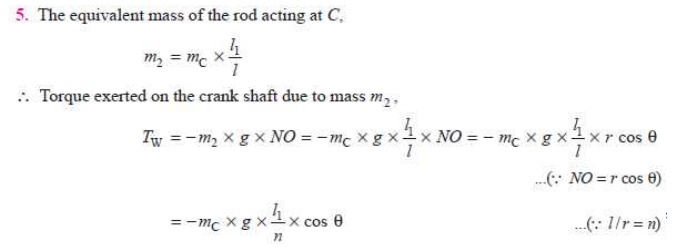
1.The mass of the connecting rod (m C) is divided into two masses. One of the mass is
placed at the crosshead pin P and the
other at the crankpin C as shown in
Fig. 15.23, so that the centre of gravity of these two masses coincides with
the centre of gravity of the rod
G.
2. Since the inertia force due to the
mass at C acts radially outwards
along the crank OC, therefore the
mass at C has no effect on the
crankshaft torque.
3. The inertia force of the mass at P may be obtained as
follows: Let
connecting rod, mC = Mass of the
l =
Length of the connecting rod,
l1 =
Length of the centre of gravity of the connecting rod from P.
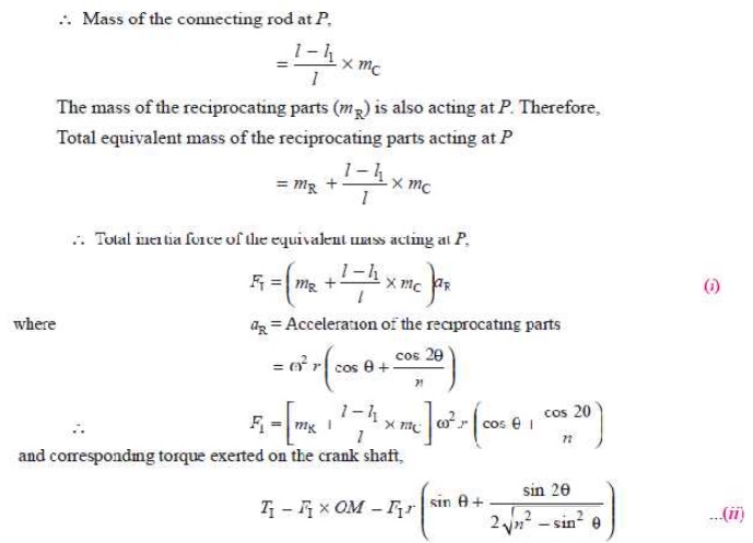
4. In
deriving the equation (ii) of the torque exerted on the
crankshaft, it is assumed that one
of the two masses is placed at C and
the other at P. This assumption does
not satisfy the condition for kinetically equivalent system of a rigid bar.
Hence to compensate for it, a correcting torque is neces- sary whose value is
given by
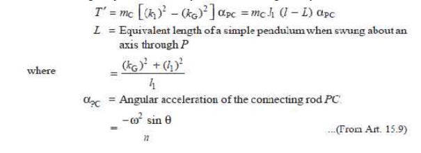
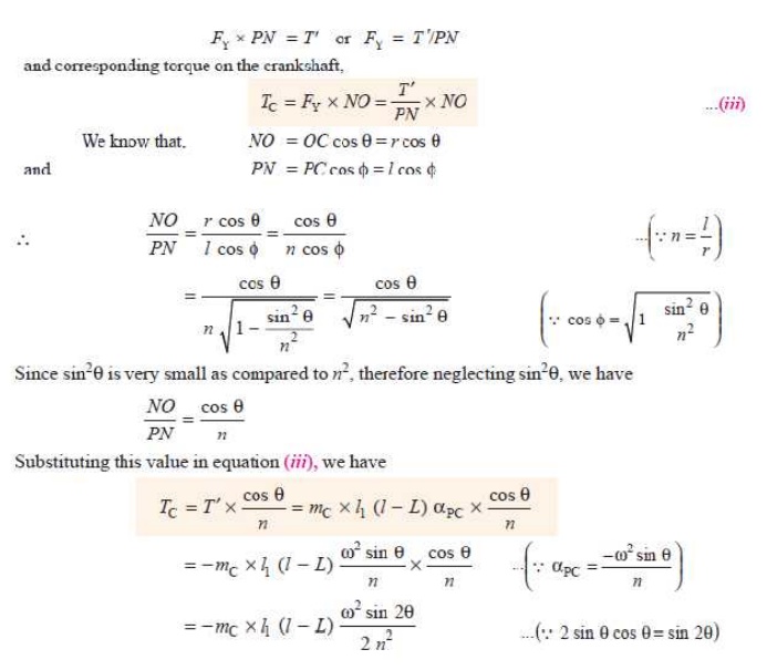
The correcting torque T' may be applied to the system by two
equal and opposite forces FYacting
through P and C. Therefore,
Q.The
crank and connecting rod lengths of an engine are 125 mm and 500 mm
respectively. The mass of the connecting rod is 60 kg and
its centre of gravity is 275 mm from the crosshead pin centre, the radius of
gyration about centre of gravity being 150 mm.
If the engine speed is 600 r.p.m. for a crank position of
45┬░ from the inner dead centre, determine, using KlienÔÇÖs or any other
construction 1. the acceleration of
the piston; 2. the magni- tude,
position and direction of inertia force due to the mass of the connecting rod.
Solution. Given : r = OC = 125 mm ; l =
PC = 500 mm; m
C = 60 kg ; PG = 275
mm ;
m C = 60 kg ; PG = 275
mm ; kG = 150 mm ; N = 600 r.p.m. or ´üĚ = 2´ü░
├Ś 600/60 = 62.84 rad/s ; ´ü▒ = 45┬░
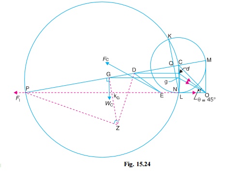
1. Acceleration of the piston
Let aP = Acceleration of the piston.
First of all, draw the configuration
diagram OCP, as shown in Fig. 15.24,
to some suitable scale, such that
OC
=
r = 125 mm ; PC = l = 500 mm ; and ´ü▒
= 45┬░.
Now, draw the KlienÔÇÖs acceleration
diagram OCQN, as shown in Fig. 15.24,
in the same manner as already discussed. By measurement,
NO
= 90 mm = 0.09 m
´üť Acceleration of the piston,
aP = ¤ë2 ├Ś NO = (62.84)2
├Ś 0.09 = 355.4 m/s Ans.
2. The magnitude,
position and direction of inertia force due to the mass of the connecting rod
The magnitude, postition and
direction of the inertia force may be obtained as follows:
(i)
Replace the connecting rod by
dynamical equivalent system of two masses,
assuming that one of the masses is placed at P and the other mass at D.
The position of the point D is
obtained as discussed in Art. 15.12.
(ii)
Locate the points G and D on NC which is the
acceleration image of the connecting
rod. Let these points are g and d on NC.
Join gO and dO. By measurement,
gO
= 103 mm = 0.103 m
´üť Acceleration of G, aG =
¤ë2 ├Ś gO, acting in
the direction from g to O.
(iii)
From point D, draw DE parallel to dO. Now E is the point through which the inertia force of the connecting rod
passes. The magnitude of the inertia force of the connecting rod is given by
FC = mC ├Ś
¤ë2 ├Ś gO = 60 ├Ś
(62.84)2 ├Ś 0.103 = 24 400
N = 24.4 kN Ans. (iv) From point E, draw a line parallel to gO, which shows the position of the
inertia force of
the connecting rod and acts in the
opposite direction of gO.
Q. The following data refer to a steam
engine:
Diameter of piston = 240 mm; stroke =
600 mm ; length of connecting rod =
1.5 m ; mass of reciprocating parts = 300 kg; mass of connecting rod = 250 kg;
speed = 125 r.p.m ; centre of gravity of connecting rod from crank pin = 500 mm
; radius of gyration of the connecting rod about an axis through the centre of
gravity = 650 mm.
Determine the magnitude and direction of the torque exerted
on the crankshaft when the crank has turned through 30┬░ from inner dead centre.
Solution. Given : D = 240 mm = 0.24 m ; L
= 600 mm or r = L/2 = 300 mm = 0.3 m ; l = 1.5 m ; mR
= 300 kg ; mC = 250 kg ; N = 125 r.p.m. or ¤ë = 2¤Ç ├Ś 25/60 = 13.1 rad/s ; GC = 500 mm = 0.5 m ; kG
= 650 mm = 0.65 m ; ╬Ş = 30┬░
The
inertia torque on the crankshaft may be determined by graphical method or
analytical method as discussed below:
1. Graphical method
First of
all, draw the configuration diagram OCP,
as shown in Fig. 15.25, to some suitable scale, such that
OC
=
r = 300 mm ; PC = l = 1.5 m ; and angle POC = ╬Ş = 30┬░.
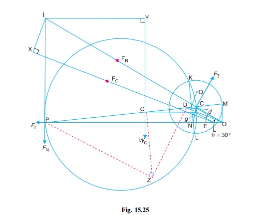
Now draw the KlienÔÇÖs acceleration
diagram OCQN, as shown in Fig. 15.25,
and complete the figure in the similar manner as discussed in Art. 15.14.
By measurement; NO = 0.28 m ; gO = 0.28 m
; IP = 1.03 m ; I X = 0.38 m ; I Y = 0.98
m, and IC = 1.7 m.
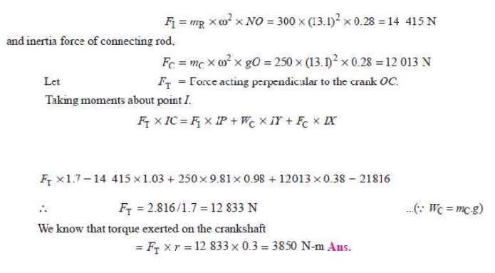
We know that inertia force of
reciprocating parts,
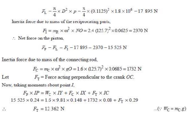
Q. The connecting rod of an internal combustion engine is 225 mm long and has a mass 1.6 kg. The mass of the piston and gudgeon pin is 2.4 kg and the stroke is 150 mm. The cylinder bore is 112.5 mm. The centre of gravity of the connection rod is 150 mm from the small end. Its radius of gyration about the centre of gravity for oscillations in the plane of swing of the connect- ing rod is 87.5 mm. Determine the magnitude and direction of the resultant force on the crank pin when the crank is at 40┬░ and the piston is moving away from inner dead centre under an effective gas presure of 1.8 MN/m2. The engine speed is 1200 r.p.m.
Solution. Given : l = PC = 225 mm = 0.225 m; mC = 1.6 kg; m R = 2.4 kg; L =
150 mm or r = L/2 = 75 mm = 0.075 m ; D = 112.5 mm = 0.1125 m ; PG = 150 mm ; kG = 87.5 mm = 0.0875 m ; ╬Ş = 40┬░ ; p = 1.8 MN/m2 = 1.8 ├Ś 10 6 N/m2 ; N = 1200 r.p.m. or ¤ë = 2¤Ç ├Ś 1200/60 = 125.7 rad/s
First of all, draw the configuration
diagram OCP, as shown in Fig. 15.27
to some suitable scale, such that OC
= r = 75 mm ; PC = l = 225 mm ; and ╬Ş = 40┬░.
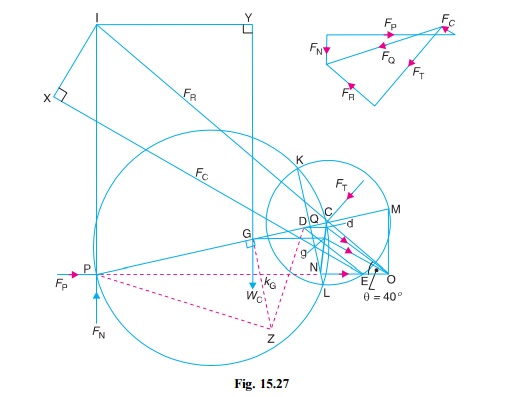
Now, draw the KlienÔÇÖs acceleration
diagram OCQN. Complete the diagram in
the same manner as discussed earlier. By measurement,
NO =
0.0625 m ; gO = 0.0685 m ; IC = 0.29 m ; IP = 0.24 m ; I Y =
0.148 m ; and IX = 0.08 m
We know that force due to gas
pressure,
Let
us now find the values of FN
and FR in magnitude and
direction. Draw the force polygon as shown in Fig. 15.25.
By measurement, FN = 3550 N; and FR
= 7550 N
The
magnitude and direction of the resultant force on the crank pin is given by FQ , which is the resultant
of FR and FT.
By measurement, FQ = 13 750 N Ans.
Related Topics