Chapter: Control Systems : Systems and their Representation
Important Short Questions, Answers: Control Systems - Systems and their Representation
SYSTEMS
AND THEIR REPRESENTATION
1.
What is
control system?
A system
consists of a number of components connected together to perform a specific
function . In a system when the output quantity is controlled by varying the
input quantity then the system is called control system.
2.
Define
open loop control system.
The
control system in which the output quantity has no effect upon the input
quantity is called open loop control system. This means that the output is not
feedback to the input for correction.
3.
Define
closed loop control system.
The
control system in which the output has an effect upon the input quantity so as
to maintain the desired output values are called closed loop control system.
4.
What are
the components of feedback control system?
The
components of feedback control system are plant, feedback path elements, error
detector actuator and controller.
5.
Distinguish
between open loop and closed loop system
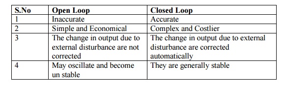
Open Loop
1.
Inaccurate
2. Simple
and Economical
3. The
change in output due to external disturbance are not corrected
4. May
oscillate and become un stable
Closed Loop
1.
Accurate
2.
Complex and Costlier
3. The
change in output due to external disturbance are corrected automatically
4. They
are generally stable
![]()
![]()
6.
Define
transfer function.
The
Transfer function of a system is defined as the ratio of the laplace transform
of output to Laplace transform of input with zero initial conditions.
7.
What are
the basic elements used for modeling mechanical translational system.
Mass M,
Kg,
Stiffness
of spring K, N/m
and
Viscous friction coefficient dashpot B, N-sec/m
8.
What are
the basic elements used for modeling mechanical rotational system?
Moment of
inertia J, Kg-m2/rad
dashpot
with rotational frictional coefficient B, N-m/(rad/sec) And torsional spring
with stiffness K ,N-m /rad.
9.
Name two
types of electrical analogous for mechanical system.
The two
types of analogies for the mechanical system are
Force
voltage and
Force
current analogy
10. What is block diagram?
A block
diagram of a system is a pictorial representation of the functions performed by
each component of the system and shows the flow of signals.
11. What are the basic components of Block diagram?
The basic
elements of block diagram are blocks, branch point and summing point.
12. What is the basis for framing the rules of
block diagram reduction technique?
The rules
for block diagram reduction technique are framed such that any modification
made on the diagram does not alter the input output relation.
13. What is a signal flow graph?
A signal
flow graph is a diagram that represents a set of simultaneous algebraic
equations
.By
taking Laplace Transform the time domain differential equations governing a
control system can be transferred to a set of algebraic equations in s-domain.
14. What is transmittance?
The
transmittance is the gain acquired by the signal when it travels from one node
to another node in signal flow graph.
15. What is sink and source?
Source is
the input node in the signal flow graph and it has only outgoing branches. Sink
is a output node in the signal flow graph and it has only incoming branches.
16. Define non touching loop.
The loops
are said to be non touching if they do not have common nodes.
17. Write Masons Gain formula.
Mason‘s
gain formula states that the overall gain of the system as follows Overall
gain,
T = T(S)
= transfer function of the system
K= Number
of forward path in the signal flow.
PK
= forward path gain of the Kth forward path
∆ = 1
–(Sum of individual loop gains) + (Sum of gain products of all possible combinations
of two non touching loops) -(Sum of gain products of all possible combinations
of three non touching loops) + …….
∆k
= (∆ for that part of the graph which is not touching Kth forward path)
18. Write the analogous electrical elements in
force voltage analogy for the elements of mechanical translational system.
Force, f
à Voltage, e
Velocity,
V à current, i
Displacement,
x à charge, q
Frictional
coefficient, B à Resistance, R
Mass, M à
inductance, L
Stiffness,
K à Inverse of capacitance 1/C
Newton‘s
second law à Kirchhoff‘s voltage law.
19. Write the analogous electrical elements in
force current analogy for the elements of mechanical translational system.
Force, f
à current, i
Velocity,
V à Voltage, e
Displacement,
x à flux, Ф
Frictional
coefficient, B à Conductance, G =1/ R
Mass, M à
capacitance C
Stiffness,
K à Inverse of inductance, 1/L
Newton‘s
second law à Kirchhoff‘s current law.
20. Write the analogous electrical elements in
torque voltage analogy for the elements of mechanical rotational system.
Torque, T
à Voltage, e
Angular
Velocity, ω à current, i
Angular
Displacement, θ à charge, q
Frictional
coefficient, B à Resistance, R
Moment of
Inertia, J à inductance, L
Stiffness
of the spring, K à Inverse of capacitance 1/C
Newton‘s
second law à kirchhoff‘s voltage law.
21. Write the analogous electrical elements in
torque current analogy for the elements of mechanical rotational system.
Torque, T
à current, i
Angular
Velocity, ω à Voltage, e
Angular
Displacement, θ à flux, Ф
Frictional
coefficient, B à Conductance, G =1/ R
Moment of
Inertia,J à capacitance C
Stiffness
of the spring, K à Inverse of inductance, 1/L
Newton‘s
second law à kirchhoff‘s current law.
22. Write the force balance equation of an ideal
mass, dashpot and spring element.
Let a
force f be applied to an ideal mass M. The mass will offer an opposing force fm
which is proportional to acceleration.
f= fm
= M d2X/dt2
Let a
force f be applied to an ideal dashpot, with viscous frictional coefficient B.
The dashpot will offer an opposing force fb which is proportional to
velocity.
f= fb
= B dX/dt
Let a
force f be applied to an ideal spring, with spring constant K. The spring will
offer an opposing force fk which is proportional to displacement.
f= fk
= K X
23. Why negative feedback is
invariably preferred in closed loop system?
The
negative feedback results in better stability in steady state and rejects any
disturbance signals.
24. State the principles of homogeneity (or)
superposition.
The
principle of superposition and homogeneity states that if the system has
responses y1(t) and y2(t) for the inputs x1(t)
and x2(t) respectively then the system response to the linear
combination of the individual outputs a1x1(t) + a2x2(t)
is given by linear combination of the individual outputs a1y1(t)+a2y2(t),
where a1, a2 are constant.
25. What are the basic properties of signal flow
graph?
The basic
properties of signal flow graph are
Signal
flow graph is applicable to linear systems. It consists of nodes and branches.
A node
adds the signal of all incoming branches and transmits this sum to all outgoing
branches.
Signals
travel along branches only in the marked direction and is multiplied by the
gain of the branch.
The algebraic
equations must be in the form of cause and effect relationship.
Related Topics