Chapter: Power Electronics : AC to AC Converters
Full Bridge Ac voltage controller
Full Bridge Ac voltage controller
It is possible to design a single phase full wave ac controller with a common cathode configuration by having a common cathode point for T1 and T2 & by adding two diodes in a full wave ac controller circuit as shown in the figure below.
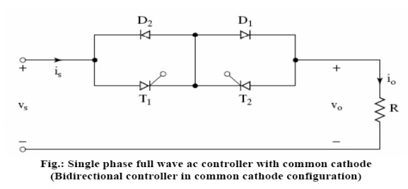
Thyristor T1 and diode D1 are forward biased during the positive half cycle of input supply. When thyristor T1 is triggered at a delay angle a. Thyristor T1 and diode D1 conduct together from ωt=a to π during the positive half cycle.
The thyristor T2 and diode D2 are forward biased during the negative half cycle of input supply. When trigged at a delay angle a, thyristor T2 and diode D2 conduct together during the negative half cycle from ωt = (π+a) to 2 π.
In this circuit as there is one single common cathode point, routing of the gate trigger pulses to the thyristor gates of T1 and T2 is simpler and only one isolation circuit is required.
But due to the need of two power diodes the costs of the devices increase. As there are two power devices conducting at the time the voltage drop across the ON devices increases and the ON state conducting losses of devices increase and hence the efficiency decreases.
SINGLE PHASE FULL WAVE AC VOLTAGE CONTROLLER USING A SINGLE THYRISTOR
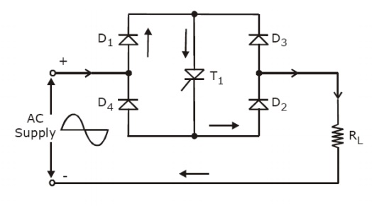
A single phase full wave ac controller can also be implemented with one thyristor and four diodes connected in a full wave bridge configuration as shown in the above figure. The our diodes ct as a bridge full wave rectifier. The voltage across the tyristor T1 and current through thyristor T1 are always unidirectional. When T1 is triggered at ωt=a, during the positive half cycle (0<=a<= π), the load current lows through D1, T1, diode D2 and through the load. With a resistive load, the thyristor current (lowing through the ON thyristor T1), the load current falls to zero at ωt= π, when the input supply voltage decreases to zero at ωt= π, the thyristor naturally turns OFF.
In the negative half cycle, diode D3 & D4 are forward biased during ωt= π to 2 π radians. When T1 is triggered at ωt= (π+a), the load current flows in the opposite direction (upward direction) through the load , through D3, T1 and D4. Thus D3, D4 and T1 conduct together during the negative half cycle to supply the load power. When the input supply voltage becomes zero at ωt= 2 π , the thyristor current (load current) falls to zero at ωt= 2 π and the thyristor T1 naturally turns OFF. The waveforms and the expression for the RMS output voltage are the same as discussed earlier for the single phase full wave ac controller.
But however if there is a large inductance in the load circuit, thyristor T1 may not be turned OFF at the zero crossing points, in every half cycle of input voltage and this may result in a loss of output control. This would require detection of the zero crossing of the load current waveorm in order to ensure guaranteed turn of of the conducting thyristor before triggering the thyristor in the next half cycle, do that we gain control on the output voltage.
In this full wave ac controller circuit using a single thyristor, as there are three power devices conducting together at the same time there is more conduction voltage drop and an increase in the ON state conduction losses and hence efficiency is also reduced.
The diode bridge rectifier and thyristor (or a power transistor) act together as a bidirectional switch which is commercially available as a single device module and it has relatively low ON state conduction loss. It can be used or bidirectional load current control and or controlling the RMS ouput voltage.
SINGLE PHASE FULLWAVE AC VOLTAGE CONTROLLER (BIDIRECTIONAL CONTROLLER) WITH RL LOAD
In this section we will discuss the equation and performance of a single phase full wave ac voltage controller with RL load. In practice most of the loads are of RL type. For example if we consider a single phase ac induction motor, the load which is the induction motor winding is an RL type of load. Where R represents the motor winding resistance and L represents the motor winding inductance.
A single phase full wave ac voltage controller circuit (bidirectional controller) with an RL load using two thyristors T1 and T2 (T1 and T2 are two SCRs) connected in parallel is shown in the figure below. In place of two thyristors a single Triac can be used to implement a full wave ac controller, if a suitable Traic is available for the desired RMS load current and the RMS output voltage rating.
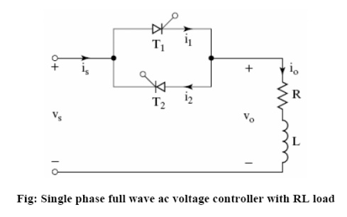
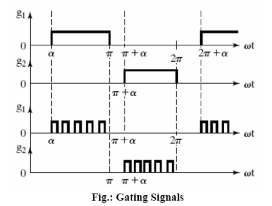
The thyristor T1 is forward biased during the positive half cycle of input supply. Let us assume that T1 is triggered at ωt= a, by applying a suitable gate trigger pulse to T1 during the positive half cycle of input supply. The output voltage across the load follows the input supply voltage when T1 is ON. The load current io flows through the thyristor T1 and through the load in the downward direction. This load current pulse lowing through T1 can be considered as the positive current pulse.
Due to the inductance in the load, the load current io, flowing through T1 would not fall to zero at ωt= π , when the input supply voltage starts to become negative.
The thyristor T1 will continue to conduct the load current until all the inductive energy store in the load inductor L is completely utilized and the load current through T1 falls to zero at ωt= β is referred to as the Extinction angle, (the value of ωt ) at which the load current falls to zero. The extinction angle β is measured from the point of the beginning of the positive half cycle of input supply to the point where the load current falls to zero.
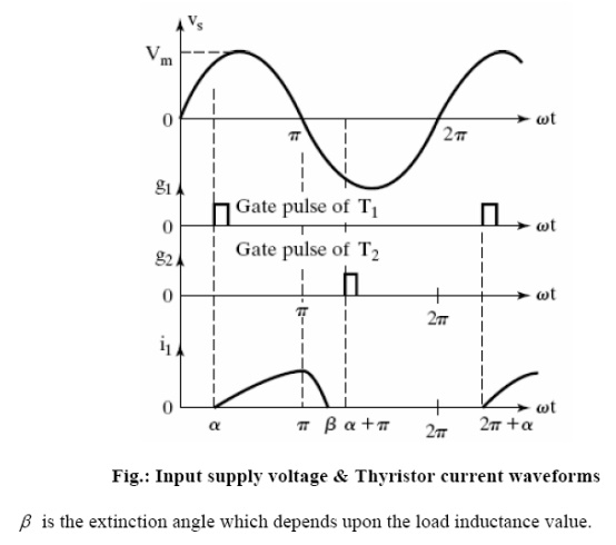
The thyristor T1 conducts from ωt= a to β. The conduction angle of T1 is δ = (β - a), which depends on the delay angle a and the load impedance angle ϕ. The waveforms of the input supply voltage, the gate trigger pulse of T1 and T2 , the thyristor current, the load current and load voltage waveforms appear as shown in the figure below.
Related Topics