Chapter: Analog and Digital Communication
Frequency Shift Keying (FSK), Minimum Shift Keying (MSK)
FREQUENCY SHIFT KEYING (FSK) , MINIMUM SHIFT KEYING
(MSK)
Minimum
Shift Keying (MSK) : The minimum frequency space that allows
the 2 fsk representing symbols 0s and 1s. Thus CP (Continuous Phase) FSK
signal with a deviation ratio if one half is defined as MSK.
Frequency
Shift Keying (FSK) : Frequency Shift Keying is the as
changing amplitude of the carrier signal with respect to the binary
information or digital signal.
The advantages of
Minimum Shift Keying :
MSK
baseband waveform are smoother compared with QPSK MSK signals have continuous
phase It does not have any amplitude variation
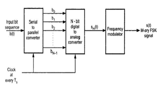
Frequency Shift
Keying (FSK)
Transmitter
The ‘N’ successive bits
are presented in parallel to digital to analog converter. These ‘N’ bits forms
a symbol at the output of digital to analog converter. There will be total 2N
= M possible symbols. The symbol is presented every Ts = N Tb
period. The output o digital to analog converter is given to a frequency
modulator. Thus depending upon the value of symbol, the frequency modulator
generates the output frequency. For every symbol, the frequency modulator
produces different frequency output. This particular frequency signal remains
at the output or one symbol duration. Thus for ‘M’ symbols, there are ‘M’
frequency signals at the output of modulator. Thus the transmitted requencies
are f0, f1, f2,………. FM-1, depending
upon the input symbol to the modulator.
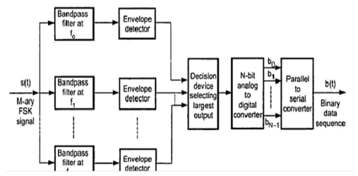
Receiver
The M-ary PSM signal is
given to the set of ‘M’ bandpass filters. The center frequencies of those
filters are f0, f1, f2,………. FM-1,. These
filters pass their particular frequency and alternate others. The envelope
detectors outputs are applied to a decision device. The decision device
produces its output depending upon the highest input. Depending upon the
particular symbol, only one envelope detector
will have higher output. The outputs of other detectors will be very
low. The output of the decision device is given to ‘N’ bit symbol in parallel.
These bits are then converted to serial bit stream by parallel to serial
converter. In some cases the bits appear in parallel. Then there is no use
serial to parallel and parallel to serial converters.
Related Topics