Chapter: Optical Communication and Networking : Transmission Characteristics of Optical Fiber
Fiber splices
Fiber splices
A permanent joint formed between two individual optical fibers in the field or factory is known as a fiber splice. Fiber splicing is frequently used to establish long-haul optical fiber links where smaller fiber lengths need to be joined, and there is no requirement for repeated connection and disconnection. Splices may be divided into two broad categories depending upon the splicing technique utilized. These are fusion splicing or welding and mechanical splicing.
Fusion splicing is accomplished by applying localized heating (e.g. by a flame or an electric arc) at the interface between two butted, prealigned fiber ends causing them to soften and fuse. Mechanical splicing, in which the fibers are held in alignment by some mechanical means, may be achieved by various methods including the use of tubes around the fiber ends (tube splices) or V-grooves into which the butted fibers are placed (groove splices). All these techniques seek to optimize the splice performance (i.e. reduce the insertion loss at the joint) through both fiber end preparation and alignment of the two joint fibers. Typical average splice insertion losses for multimode fibers are in the range 0.1 to 0.2 dB which is generally a better performance than that exhibited by demountable connections.
It may be noted that the insertion losses of fiber splices are generally much less than the possible Fresnel reflection loss at a butted fiber–fiber joint. This is because there is no large step change in refractive index with the fusion splice as it forms a continuous fiber connection, and some method of index matching (e.g. a fluid) tends to be utilized with mechanical splices
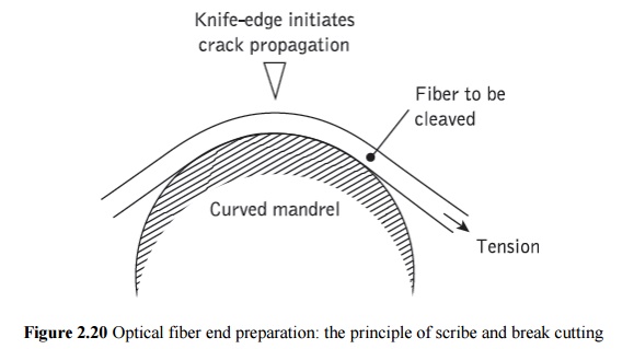
A requirement with fibers intended for splicing is that they have smooth and square end faces. In general this end preparation may be achieved using a suitable tool which cleaves the fiber as illustrated in Figure 2.20. This process is often referred to as scribe and break or score and break as it involves the scoring of the fiber surface under tension with a cutting tool (e.g. sapphire, diamond, tungsten carbide blade). The surface scoring creates failure as the fiber is tensioned and a clean, reasonably square fiber end can be produced.
Figure 2.20 illustrates this process with the fiber tensioned around a curved mandrel. However, straight pull, scribe and break tools are also utilized, which arguably give better results.
1. Fusion splices
The fusion splicing of single fibers involves the heating of the two prepared fiber ends to their fusing point with the application of sufficient axial pressure between the two optical fibers. It is therefore essential that the stripped (of cabling and buffer coating) fiber ends are adequately positioned and aligned in order to achieve good continuity of the transmission medium at the junction point. Hence the fibers are usually positioned and clamped with the aid of an inspection microscope.
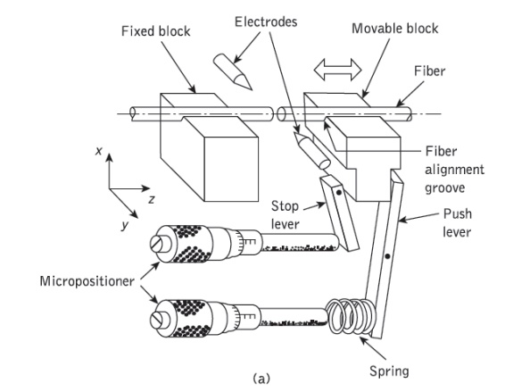
Flame heating sources such as microplasma torches (argon and hydrogen) and oxhydricmicroburners (oxygen, hydrogen and alcohol vapor) have been utilized with some success. However, the most widely used heating source is an electric arc. This technique offers advantages of consistent, easily controlled heat with adaptability for use under field conditions.
A schematic diagram of the basic arc fusion method is given in Figure 2.21(a) illustrating how the two fibers are welded together. Figure 2.21(b) shows a development of the basic arc fusion process which involves the rounding of the fiber ends with a low-energy discharge before pressing the fibers together and fusing with a stronger arc.
This technique, known as prefusion, removes the requirement for fiber end preparation which has a distinct advantage in the field environment. It has been utilized with multimode fibers giving average splice losses of 0.09 db.
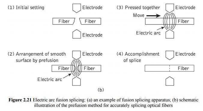
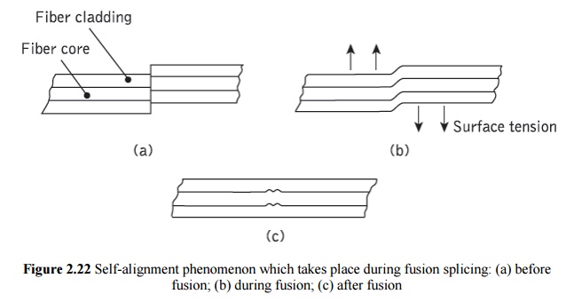
Fusion splicing of single-mode fibers with typical core diameters between 5 and 10 µm presents problems of more critical fiber alignment (i.e. lateral offsets of less than 1 µm are required for low loss joints). However, splice insertion losses below 0.3 dB may be achieved due to a self-alignment phenomenon which partially compensates for any lateral offset.
Self-alignment, illustrated in Figure 2.22, is caused by surface tension effects between the two fiber ends during fusing. An early field trial of single-mode fiber fusion splicing over a 31.6 km link gave mean splice insertion losses of 0.18 and 0.12 dB at wavelengths of 1.3 and 1.55 µm respectively. Mean splice losses of only 0.06 dB have also been obtained with a fully automatic single-mode fiber fusion splicing machine weaken the fiber in the vicinity of the splice. It has been found that even with careful handling, the tensile strength of the fused fiber may be as low as 30% of that of the uncoated fiber before fusion.
The fiber fracture generally occurs in the heat affected zone adjacent to the fused joint. The reduced tensile strength is attributed to the combined effects of surface damage caused by handling, surface defect growth during heating and induced residential stresses due to changes in chemical composition. It is therefore necessary that the completed splice is packaged so as to reduce tensile loading upon the fiber in the vicinity of the splice.
2. Mechanical splices
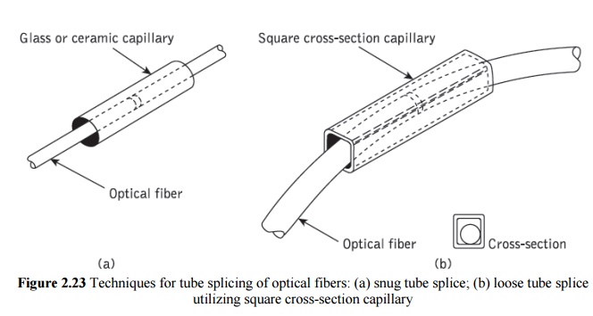
A number of mechanical techniques for splicing individual optical fibers have been developed. A common method involves the use of an accurately produced rigid alignment tube into which the prepared fiber ends are permanently bonded. This snug tube splice is illustrated in Figure 2.23(a) and may utilize a glass or ceramic capillary with an inner diameter just large enough to accept the optical fibers. Transparent adhesive (e.g. epoxy resin) is injected through a transverse bore in the capillary to give mechanical sealing and index matching of the splice. Average insertion losses as low as 0.1 dB have been obtained with multimode graded index and single-mode fibers using ceramic capillaries. However, in general, snug tube splices exhibit problems with capillary tolerance requirements. Hence as a commercial product they may exhibit losses of up to 0.5 dB.
Mechanical splicing technique which avoids the critical tolerance requirements of the snug tube splice is shown in Figure 2.23(b). This loose tube splice uses an oversized square-section metal tube which easily accepts the prepared fiber ends. Transparent adhesive is first inserted into the tube followed by the fibers. The splice is self-aligning when the fibers are curved in the same plane, forcing the fiber ends simultaneously into the same corner of the tube, as indicated in Figure 2.23(b). Mean splice insertion losses of 0.073 dB have been achieved using multimode graded index fibers with the loose tube approach.
Other common mechanical splicing techniques involve the use of grooves to secure the fibers to be jointed. A simple method utilizes a V-groove into which the two prepared fiber ends are pressed. The V-groove splice which is illustrated in Figure 2.24(a) gives alignment of the prepared fiber ends through insertion in the groove. The splice is made permanent by securing the fibers in the V-groove with epoxy resin. Jigs for producing Vgroove splices have proved quite successful, giving joint insertion losses of around 0.1 dB
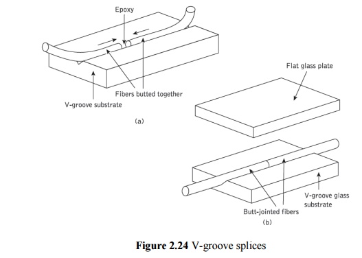
V-groove splices formed by sandwiching the butted fiber ends between a V-groove glass substrate and a flat glass retainer plate, as shown in Figure 2.24(b), have also proved very successful in the laboratory. Splice insertion losses of less than 0.01 dB when coupling single-mode fibers have been reported using this technique. However, reservations are expressed regarding the field implementation of these splices with respect to manufactured fiber geometry, and housing of the splice in order to avoid additional losses due to local fiber bending.
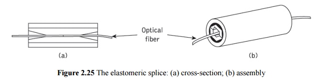
A further variant on the V-groove technique is the elastic tube or elastomeric splice shown in Figure 2.25. The device comprises two elastomeric internal parts, one of which contains a V-groove. An outer sleeve holds the two elastic parts in compression to ensure alignment of the fibers in the V-groove, and fibers with different diameters tend to be centered and hence may be successfully spliced. Although originally intended for multimode fiber connection, the device has become a widely used commercial product which is employed with single-mode fibers, albeit often as a temporary splice for laboratory investigations. The splice loss for the elastic tube device was originally reported as 0.12 dB or less but is generally specified as around 0.25 dB for the commercial product. In addition, index-matching gel is normally employed within the device to improve its performance.
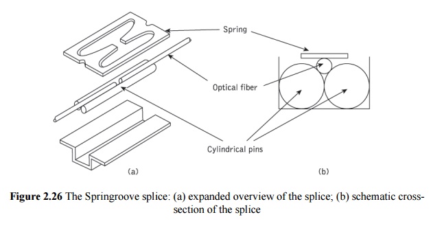
A slightly more complex groove splice known as the Springroove® splice utilized a bracket containing two cylindrical pins which serve as an alignment guide for the two prepared fiber ends. The cylindrical pin diameter was chosen to allow the fibers to protrude above the cylinders, as shown in Figure 2.26(a). An elastic element (a spring) was used to press the fibers into a groove and maintain the fiber end alignment, as illustrated in Figure 2.26(b). The complete assembly was secured using a drop of epoxy resin. Mean splice insertion losses of 0.05 dB were obtained using multimode graded index fibers with the Springroove splice. This device found practical use in Italy.
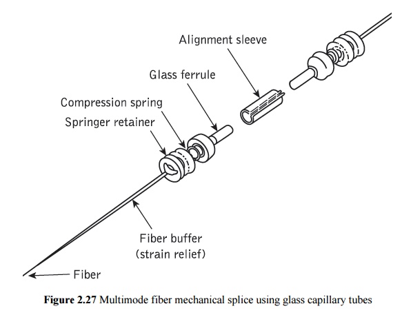
An example of a secondary aligned mechanical splice for multimode fiber is shown in Figure 2.27. This device uses precision glass capillary tubes called ferrules as the secondary elements with an alignment sleeve of metal or plastic into which the glass tubed fibers are inserted. Normal assembly of the splice using 50 µm core diameter fiber yields an average loss of around 0.2 dB.
3. Multiple splices
Multiple simultaneous fusion splicing of an array of fibers in a ribbon cable has been demonstrated for both multimode and single-mode fibers. In both cases a 12-fiber ribbon was prepared by scoring and breaking prior to pressing the fiber ends onto a contact plate to avoid difficulties with varying gaps between the fibers to be fused.
An electric are fusing device was then employed to provide simultaneous fusion. Such a device is now commercially available to allow the splicing of 12 fibers simultaneously in a time of around 6 minutes, which requires only 30 seconds per splice. Splice losses using this device with multimode graded index fiber range from an average of 0.04 dB to a maximum of 0.12 dB, whereas for single-mode fiber the average loss is 0.04 dB with a 0.4 dB maximum.
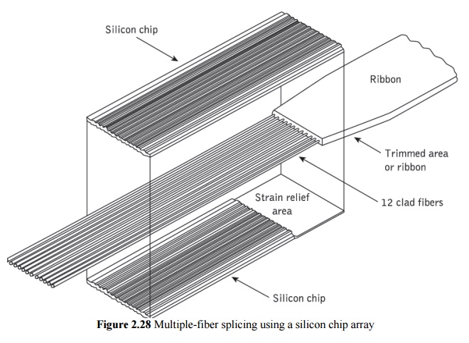
A simple technique employed for multiple simultaneous splicing involves mechanical splicing of an array of fibers, usually in a ribbon cable. The V-groove multiple-splice secondary element comprising etched silicon chips has been used extensively in the United States for splicing multimode fibers. In this technique a 12-fiber splice is prepared by stripping the ribbon and coating material from the fibers. Then the 12 fibers are laid into the trapezoidal* grooves of a silicon chip using a comb structure, as shown in Figure 2.28. The top silicon chip is then positioned prior to applying epoxy to the chip–ribbon interface. Finally, after curing, the front end face is ground and polished.
The process is normally carried out in the factory and the arrays are clipped together in the field, putting index-matching silica gel between the fiber ends. The average splice loss obtained with this technique in the field is 0.12 dB, with the majority of the loss resulting from intrinsic fiber mismatch. Major advantages of this method are the substantial reduction in splicing time (by more than a factor of 10) per fiber and the increased robustness of the final connection. Although early array splicing investigations using silicon chips demonstrated the feasibility of connecting 12*12 fiber arrays, in practice only single 12-fiber ribbons have been spliced at one time due to concerns in relation to splice tolerance and the large number of telecommunication channels which would be present in the two-dimensional array.
An alternative V-groove flat chip molded from a glass-filled polymer resin has been employed in France. Moreover, direct mass splicing of 12-fiber ribbons has also been accomplished [Ref. 63]. In this technique simultaneous end preparation of all 24 fibers was achieved using a ribbon grinding and polishing procedure. The ribbons were then laid in guides and all 12 fibers were positioned in grooves in the glass-filled plastic
Related Topics