Chapter: Optical Communication and Networking : Transmission Characteristics of Optical Fiber
Fiber connectors
Fiber connectors
Demountable fiber connectors are more difficult to achieve than optical fiber splices. This is because they must maintain similar tolerance requirements to splices in order to couple light between fibers efficiently, but they must accomplish it in a removable fashion. Also, the connector design must allow for repeated connection and disconnection without problems of fiber alignment, which may lead to degradation in the performance of the transmission line at the joint. Hence to operate satisfactorily the demountable connector must provide reproducible accurate alignment of the optical fibers.
In order to maintain an optimum performance the connection must also protect the fiber ends from damage which may occur due to handling (connection and disconnection), must be insensitive to environmental factors (e.g. moisture and dust) and must cope with tensile load on the cable. Additionally, the connector should ideally be a low-cost component which can be fitted with relative ease. Hence optical fiber connectors may be considered in three major areas, which are:
ü the fiber termination, which protects and locates the fiber ends;
ü the fiber end alignment to provide optimum optical coupling;
ü the outer shell, which maintains the connection and the fiber alignment, protects the fiber ends from the environment and provides adequate strength at the joint.
1. Cylindrical ferrule connectors
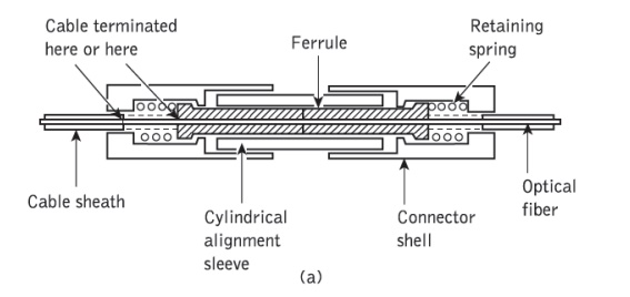
The basic ferrule connector (sometimes referred to as a concentric sleeve connector), which is perhaps the simplest optical fiber connector design.The two fibers to be connected are permanently bonded (with epoxy resin) in metal plugs known as ferrules which have an accurately drilled central hole in their end faces where the stripped (of buffer coating) fiber is located. Within the connector the two ferrules are placed in an alignment sleeve which, using accurately machined components, allows the fiber ends to be butt jointed. The ferrules are held in place via a retaining mechanism which, in the example shown in Figure 2.29(a), is a spring.
It is essential with this type of connector that the fiber end faces are smooth and square (i.e. perpendicular to the fiber axis). This may be achieved with varying success by:
ü cleaving the fiber before insertion into the ferrule;
ü inserting and bonding before cleaving the fiber close to the ferrule end face;
ü using either (a) or (b) and polishing the fiber end face until it is flush with the end of the ferrule.
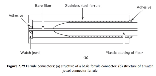
Polishing the fiber end face after insertion and bonding provides the best results but it tends to be time consuming and inconvenient, especially in the field. The fiber alignment accuracy of the basic ferrule connector is largely dependent upon the ferrule hole into which the fiber is inserted. Hence, some ferrule connectors have incorporated a watch jewel in the ferrule end face (jeweled ferrule connector), as illustrated in Figure 2.29(b). In this case the fiber is centered with respect to the ferrule through the watch jewel hole. The use of the watch jewel allows the close diameter and tolerance requirements of the ferrule end face hole to be obtained more easily than simply through drilling of the metallic ferrule end face alone. Nevertheless, typical concentricity errors between the fiber core and the outside diameter of the jeweled ferrule are in the range 2 to 6 µm giving insertion losses in the range 1 to 2 dB with multimode step index fibers
2. Expanded beam connectors
An alternative to connection via direct butt joints between optical fibers is offered by the principle of the expanded beam. Fiber connection utilizing this principle is illustrated in Figure 2.30, which shows a connector consisting of two lenses for collimating and refocusing the light from one fiber into the other.
The use of these interposed optics makes the achievement of lateral alignment much less critical than with a butt-jointed fiber connector.
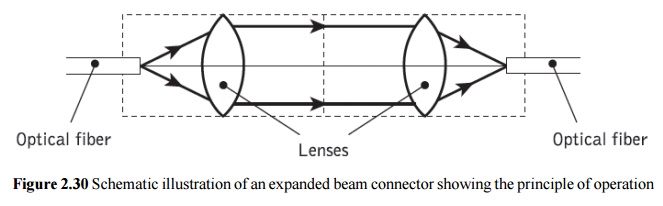
Also, the longitudinal separation between the two mated halves of the connector ceases to be critical. However, this is achieved at the expense of more stringent angular alignment. Nevertheless, expanded beam connectors are useful for multifiber connection and edge connection for printed circuit boards where lateral and longitudinal alignment are frequently difficult to achieve.
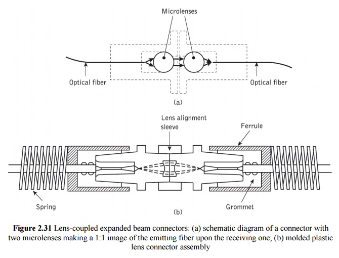
Two examples of lens-coupled expanded beam connectors are illustrated in Figure 2.31. The connector shown in Figure 2.31(a) utilized spherical microlenses for beam expansion and reduction. It exhibited average losses of 1 dB which were reduced to 0.7 dB with the application of an antireflection coating on the lenses and the use of graded index fiber of 50 µm core diameter. A similar configuration has been used for single-mode fiber connection in which the lenses have a 2.5 mm diameter. Again with antireflection-coated lenses, average losses around 0.7 dB were obtained using single-mode fibers of 8 µm core diameter. Furthermore, successful single-mode fiber
connection has been achieved with a much smaller (250 µm diameter) sapphire ball lens expanded beam design.
In this case losses in the range 0.4 to 0.7 dB were demonstrated over 1000 connections. Figure 2.31(b) shows an expanded beam connector which employs a molded spherical lens. The fiber is positioned approximately at the focal length of the lens in order to obtain a collimated beam and hence minimize lens-to-lens longitudinal misalignment effects. A lens alignment sleeve is used to minimize the effects of angular misalignment which, together with a ferrule, grommet, spring and external housing, provides the complete connector structure. The repeatability of this relatively straightforward lens design was found to be good, incurring losses of around 0.7 dB.
Related Topics