Chapter: Electrical machines : Single Phase Induction Motor and Special Machines
Equvalent Circuit of Single Phase Induction Motor
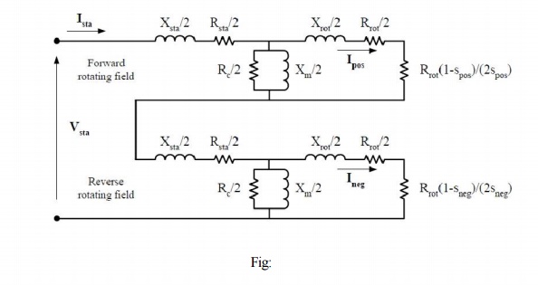
EQUVALENT CIRCUIT OF SINGLE PHASE INDUCTION MOTOR
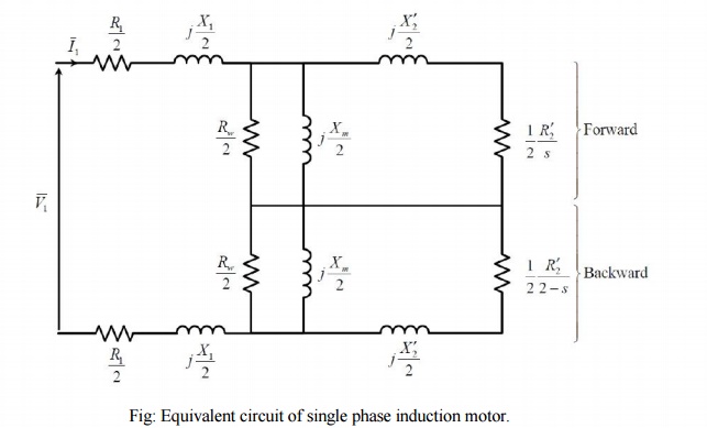
The equivalent circuit of single phase induction motor is shown below (Fig:)
Determination of Equivalent Circuit Parameters of Single Phase Induction motor
It is possible to find the parameters of the equivalent circuit of the single phase induction motor experimentally as shown in Fig.4.4. For this purpose, three tests should be conducted:
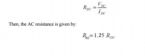
1- The DC Test:
The DC resistance of the stator can be measured by applying DC current to the terminals of the main winding and taking the reading of the voltage and the current (or using ohmmeter) and determine the DC resistance as follows:
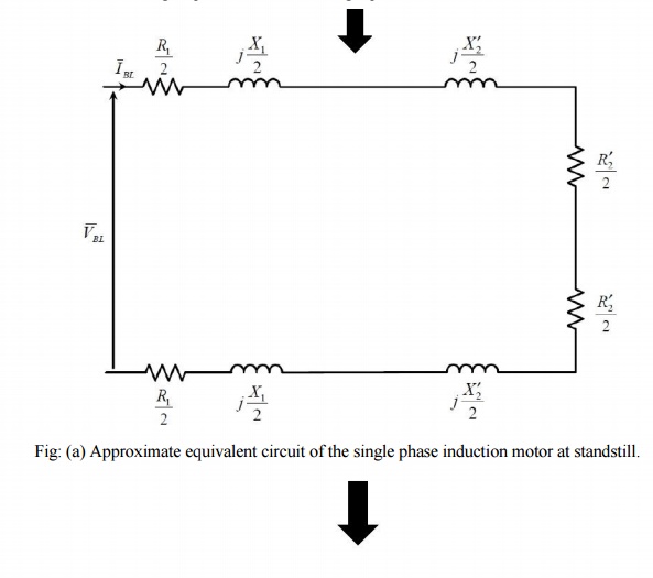
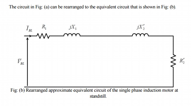
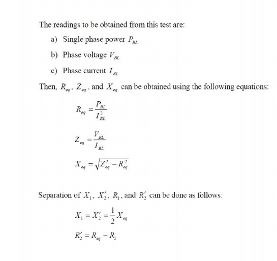
2-The Blocked Rotor Test:
When the rotor is locked (i.e. prevented from running), Sb = Sf = 1. The secondary impedances become much less than the magnetizing branches and the corresponding equivalent circuit becomes that of Fig:.
3-The No Load Test:
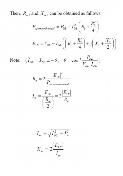
When the induction motor is allowed to run freely at no load, the forward slip Sf approaches zero and the backward slip Sb approaches 2 (Sf = s, Sb = 2-s). The secondary forward impedance becomes very large with respect to the magnetizing branch, while the secondary backward impedance becomes very small if compared with the magnetizing branch. Accordingly, the equivalent circuit corresponding to these operating conditions can be approximated by that of Fig:.
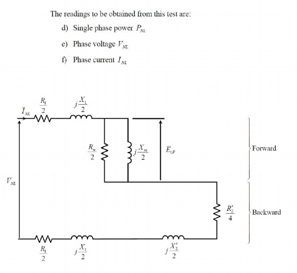
Fig: (a) Approximate equivalent circuit of the single phase induction motor at no load.
The circuit in Fig: (a) can be rearranged to the equivalent circuit that is shown in Fig: (b)
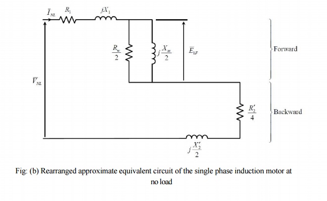
Fig: (b) Rearranged approximate equivalent circuit of the single phase induction motor at no load
Related Topics