Chapter: mechanical : Engineering Graphics
Development of Surfaces and Isometric Projection
DEVELOPMENT OF SURFACES AND ISOMETRIC PROJECTION
Development
of lateral surfaces of vertical prism, cylinder pyramid, and cone truncated by
surfaces of inclined to HP alone. Development of surfaces of vertical cylinder
and prism with cylindrical cut outs perpendicular to the axis. Isometric
projection of solids like prism, pyramid, cylinder and cone; combination of any
two; truncation when solid is in simple vertical position, by a cutting plane
inclined to HP.
Development of
surfaces:
A layout
of the complete surface of a three dimensional object on a plane surface is
called its development or pattern. Development is a term frequently used in
sheet metal work where it means the unfolding or unrolling of a detail into a
flat sheet called a pattern
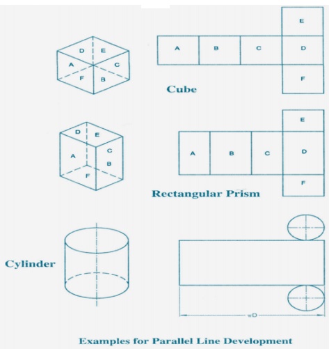
There are
three methods of pattern development; (i) Parallel line, (ii) Radial line and
(iii) Triangulation.
Parallel Line
Method:
This
method can only be used to develop objects (or parts thereof) having a constant
cross-section for their full length, for example, prisms and cylinders and
related forms. Parallel lines, parallel to the axis of the detail, are shown on
a view which shows them as their true lengths.
1. After
drawing the given views, determine the view in which the right section of the
solid appears as an edge view. Here it should be noted that top views of right
prisms and cylinders are equivalent to their right sections will have to be
found
in the
form of an auxiliary view.
2. Layout
the stretch-out line of the development parallel to the edge view of the right
section.
3.
Locate the distance between lateral comer edges by
measuring from the true size views in the right section and then transferring
these measurements to the stretch-out line. Name their points.
4. Draw the
lateral fold lines perpendicular to the stretch-out line through the points
already plotted.
5. The
development should be commenced at the shortest line, so that the least amount
of welding or other joining effort is required.
6. Join all
end points forming the boundary of the pattern in proper order. Only the
boundary of the pattern should be made bold, leaving all other lines as thin
lines.
7. Check up
that the point where the development ends is the same point as the beginning
point on the right section.
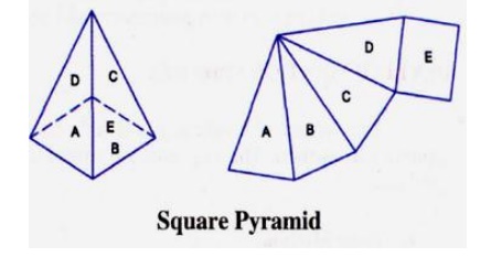
Radial Line Method:
This
method of development is used for right and oblique pyramids and cones. It
employs radial lines which are slant edges from vertex to base comer points for
pyramids, and radial surface lines on the cone surface from the vertex to the
base.
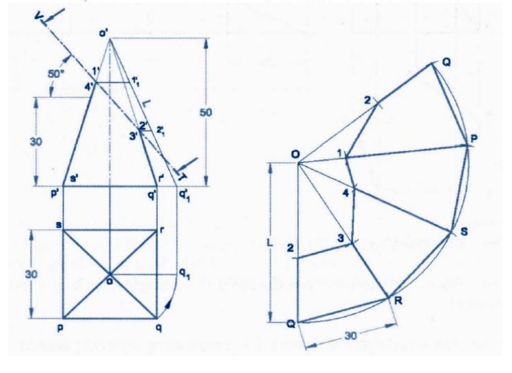
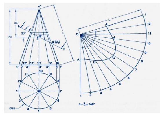
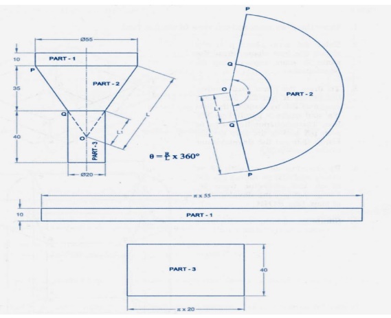
Development of Right Cones
The
development of any right cone is a sector of a circle since the radial surface
Lines are all of the same true length. The angle at centre of the sector
depends on the base radius and the slant height of the cone. Let the radius of
the base of the cone be R, the slant
height of the cone be L, and the
angle at the centre of the development be θ.
θ = (Radius of the base circle /True
slant length) X 360 =( R / L ) X 360
In this method of development the
surface of the object is divided
into a number of triangles. The true sizes of the triangles are found and then
these triangles are drawn in order, side by side, to produce the pattern. It is simple to realize that to find
the true sizes of the triangles, it is first necessary to find the true length
of their sides.
1. When the
top and bottom edges of a sheet metal detail are parallel to the HP the true lengths of these edges may
be taken directly from the top view.
2. In case
of circular edges, chordal distance may be taken and transferred to the
development. Though such lengths are not theoretically accurate they are
satisfactory for development work.
3.
For all transition pieces having inclined top and
bottom edges, TL construction must
be carried out if these edges are curved.
4. A well
defined labeling system should be used in order that the construction technique
may be progressive and easy to understand.
Isometric Projection:
The
isomeric projection of an object is obtained on a vertical plane of projection
by placing the object in such a way that its three mutually perpendicular edges
make equal inclinations with the plane of projection. Since the three mutually
perpendicular edges of an object are projected in the isometric projection at
equal axonometric angles, the angles between those edges in the isometric
projection will be at 12°. The lengths of the three mutually perpendicular
edges of the object in the isometric projection are foreshortened in the same
proportion.
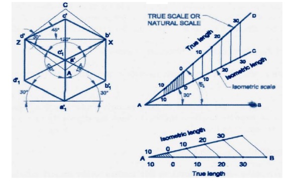
Isometric Scale:
In the isometric projection, all the edges of an object
along the direction of the three isometric axes are foreshortened to 0.816 times their actual lengths. To
facilitate an easy and quick method of measurement of the lengths of the
different edges in their reduced sizes while drawing the isometric projection
of the object, a special scale called isometric
scale is constructed.
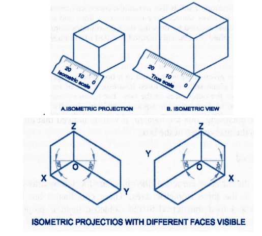
The view
drawn to the actual scale is called the isometric
view or Isometric Drawing while that
drawn using the isometric scale is
called the Isometric Projection.
Importance Points in Isometric:
1.
For drawing the isometric, the object must be
viewed such that either the front -right or the left edges becomes nearest.
2.
All vertical edges of the object remain vertical in
isometric
The
horizontal edges of the object which are parallel to the isometric axes are
drawn at 30° to the horizontal.
4. The
inclined edges which are not parallel to the isometric axes should not be drawn
at the given inclination in isometric. These inclined edges are drawn by first
locating the end points in isometric and then joined.
5. All
circles are represented as ellipses in isometric.
6. All
construction lines have to be retained as thin lines and the visible edges are
to be shown as thick lines.
7. Generally
the hidden edges need not be shown in isometric unless otherwise required
either for locating a comer, or an edge, or face, or mentioned.
8. Unless
otherwise specifically mentioned to draw the isometric view or isometric
drawing all dimension lines parallel to the isometric unless otherwise if
mentioned.
9. No
dimensions are indicated in isometric unless otherwise mentioned.
The given
orthographic views need not be drawn unless required for consideration
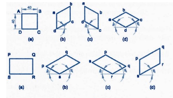
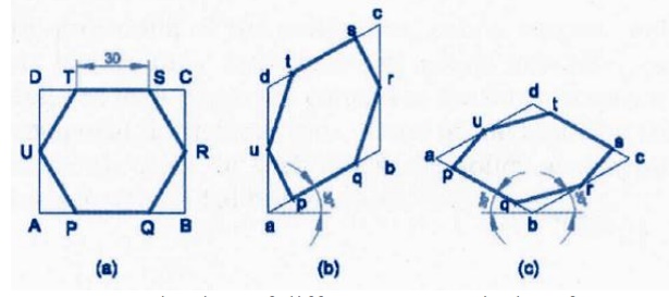
Isometric
view of different geometrical surfaces
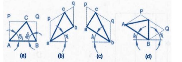
Isometric
view of triangle
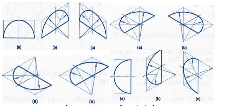
Isometric
view of semi circle
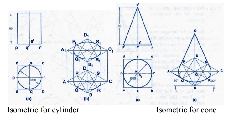
Isometric
for cylinder Isometric
for cone
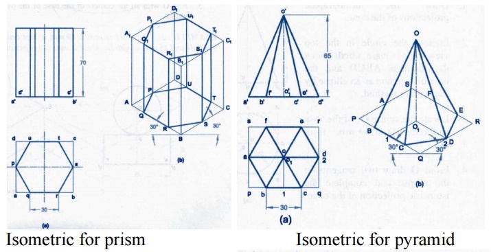
Isometric
for prism Isometric
for pyramid
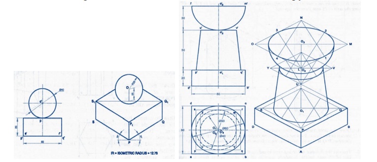
Isometric
for combination solid
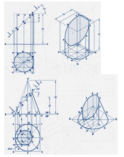
Isometric
for cutting model in cylinder and cone
Isometric
for cutting model in cone and pyramid
Isometric
for cutting model square pyramid
Important Questions
1.
A cylinder of diameter 40mm and
height50mm is resting vertically on one of its end on the hp. It is cut by a
plane perpendicular to the vp and inclined at 30®to the hp. The plane meets the
axis at a point 30mm from the base. Draw the development of the lateral surface
of the lower portions of the truncated cylinder.
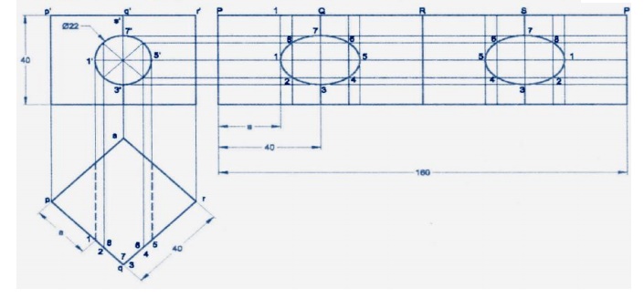
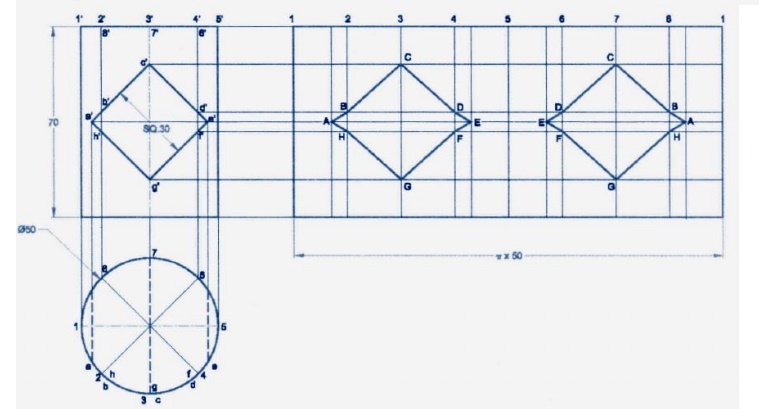
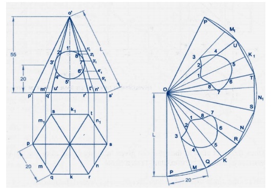
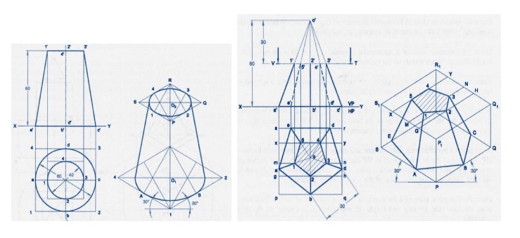
2.
A hexagonal prism of base side 20mm
and height 40mm has a square hole of side 16mm at the centre. The axes of the
square and hexagon coincide. One of the faces of the square is parallel to the
face of the hexagon. Draw the isometric projection of the prism with hole to
full scale.
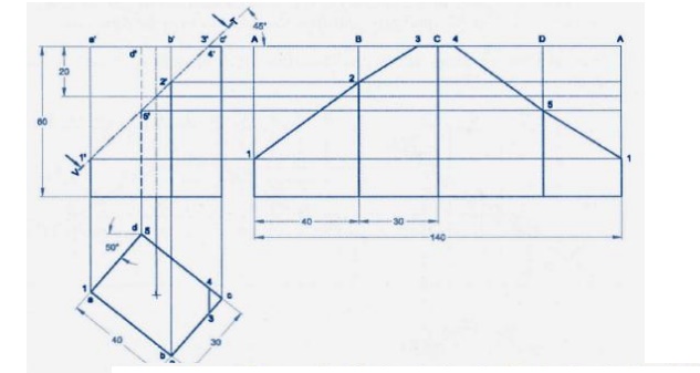
3. A right circular
cone, 40mm base and 50mm height, rests on its base on HP. A section plane
perpendicular to VP and inclined to HP AT 45®cuts the cone bisecting axis. Draw
projections of the truncated cone and develop its lateral surface.
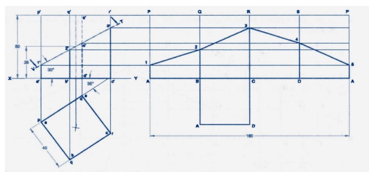
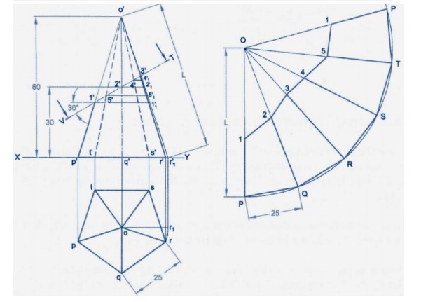
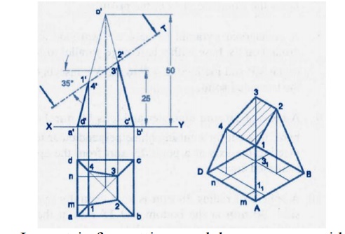
4.
A pentagonal pyramid of 40mm edge of
base and height 70mm rests with its base on HP. One of the bases edges is
perpendicular to VP and line on the left of axis of the pyramid. A section
plane perpendicular to VP and inclined at 30®to VP cut the axis of the pyramid
at a point 30mm above the base of the pyramid. Draw the isometric projection of
the truncated pyramid.
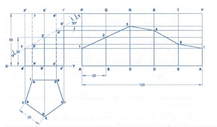
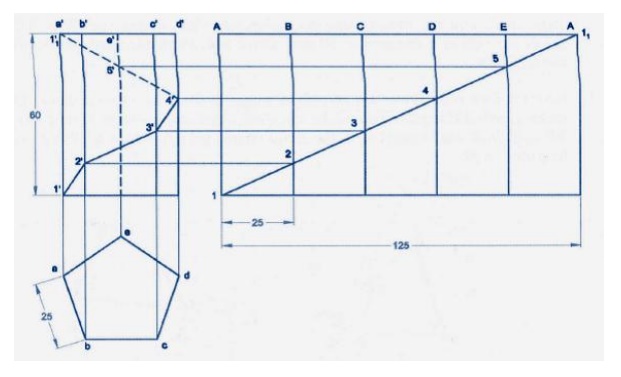
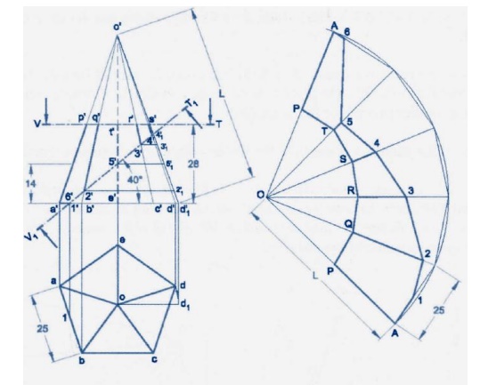
5.
A pentagonal pyramid of base edge
25mm and height 60mm rests vertically on its base on the HP such that one of
its base edge parallel to VP. It is cut by a plane, inclined at 60 to HP and
passes through a point 35mm from the apex. Draw the development of the lateral
surface of the pyramid.
6.
An object consists of a hemispherical
vessel of 80mm diameter which is placed centrally over a cylinder of 50mm diameter and height of
60mm. the cylinder in turn is placed centrally over a square prism of 60mm base
side and 20mmh height. Draw the isometric projection of the object.
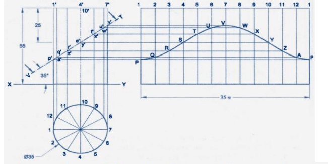
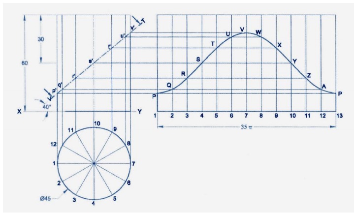
7.
Draw the development of the lateral
surface of the lower portion of a cylinder of diameter 50mm and axis 70mm. the
solid is cut by a sectional plane inclined at 40®to HP and perpendicular to VP
and passing through the midpoint of the axis.
8.
Draw the isometric projection of the
object from the view shown in figure.
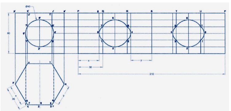
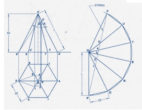
9.
A regular hexagonal pyramid side of
base 20mm and height 60mm is resting vertically on its base on HP, such that
two of the sides of the base are perpendicular the VP. It is cut by a plane
inclined at 40® to HP and
perpendicular to VP. The cutting plane bisects the axis of the
pyramid. Obtain the development of the lateral surface of the truncated
pyramid.
10.
A cylinder of 50mm diameter and 75mm
height stands with its base on HP. It is cut by a section plane inclined at 45®
to HP and perpendicular to VP passing through a point on the axis 20mm below
the top end. Draw the isometric projection at the truncated cylinder.
11.
A cylinder of diameter 40mm and
height 50mm is resting vertically on one of its ends on the HP. It is cut by a
plane perpendicular to the VP and inclined at 30® to the HP. The plane meets
the axis at a point 30mm from the base. Draw the development of the lateral
surface of the lower portion of the truncated cylinder.
12.
A hexagonal prism of base side 20mm
and height 40mm has a square hole of side 16mm at center. The axis of the
square and hexagon coincide. One of the faces of the square hole is parallel to
the face of the hexagon. Draw the isometric projection of the prism with hole
of full scale.
Related Topics