Chapter: Measurements and Instrumentation : Comparison Methods of Measurements
D.C and A.C Potentiometers
D.C &
A.C Potentiometers
An
instrument that precisely measures an electromotive force (emf) or a voltage by
opposing to it a known potential drop established by passing a definite current
through a resistor of known characteristics. (A three-terminal resistive
voltage divider is sometimes also called a potentiometer.) There are two ways
of accomplishing this balance: (1) the current I may be held at a fixed value and the resistance R across which the IR drop is opposed to the unknown may be varied; (2) current may be
varied across a fixed resistance to achieve the needed IR drop.
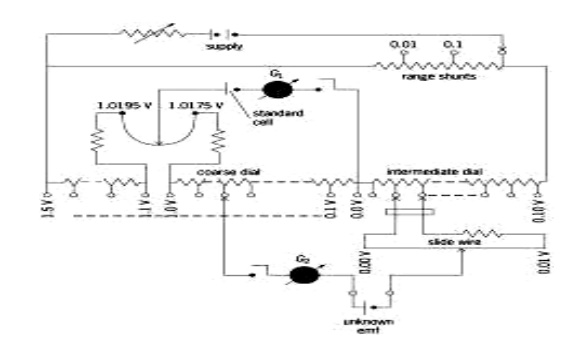
The
essential features of a general-purpose constant-current instrument are shown
in the illustration. The value of the current is first fixed to match an IR drop to the emf of a reference
standard cell. With the standard-cell dial set to read the emf of the reference
cell, and the galvanometer (balance detector) in position G1, the resistance of the supply branch of the circuit is adjusted
until the IR drop in 10 steps of the
coarse dial plus the set portion of the standard-cell dial balances the known
reference emf, indicated by a null reading of the galvanometer. This adjustment
permits the potentiometer to be read directly in volts. Then, with the
galvanometer in position G2, the
coarse, intermediate, and slide-wire dials are adjusted until the galvanometer
again reads null. If the potentiometer current has not changed, the emf of the
unknown can be read directly from the dial settings. There is usually a
switching arrangement so that the galvanometer can be quickly shifted between
positions 1 and 2 to check that the current has not drifted from its set value.

Circuit
diagram of a general-purpose constant-current potentiometer, showing essential
features Potentiometer techniques may also be used for current measurement, the
unknown current being sent through a known resistance and the IR drop opposed by balancing it at the
voltage terminals of the potentiometer. Here, of course, internal heating and
consequent resistance change of the current-carrying resistor (shunt) may be a
critical factor in measurement accuracy; and the shunt design may require
attention to dissipation of heat resulting from its I2R power
consumption.
Potentiometer
techniques have been extended to alternating-voltage measurements, but
generally at a reduced accuracy level (usually 0.1% or so). Current is set on
an ammeter which must have the same response on ac as on dc, where it may be
calibrated with a potentiometer and shunt combination. Balance in opposing an
unknown voltage is achieved in one of two ways: (1) a slide-wire and
phase-adjustable supply; (2) separate in-phase and quadrature adjustments on
slide wires supplied from sources that have a 90° phase difference. Such
potentiometers have limited use in magnetic testing.
An
instrument that precisely measures an electromotive force (emf) or a voltage by
opposing to it a known potential drop established by passing a definite current
through a resistor of known characteristics. (A three-terminal resistive
voltage divider is sometimes also called a potentiometer.) There are two ways
of accomplishing this balance: (1) the current I may be held at a fixed value and the resistance R across which the IR drop is opposed to the unknown may be varied; (2) current may be
varied across a fixed resistance to achieve the needed IR drop.
The
essential features of a general-purpose constant-current instrument are shown
in the illustration. The value of the current is first fixed to match an IR drop to the emf of a reference
standard cell. With the standard-cell dial set to read the emf of the reference
cell, and the galvanometer (balance detector) in position G1, the resistance of the supply branch of the circuit is adjusted
until the IR drop in 10 steps of the
coarse dial plus the set portion of the standard-cell dial balances the known
reference emf, indicated by a null reading of the galvanometer. This adjustment
permits the potentiometer to be read directly in volts. Then, with the
galvanometer in position G2, the
coarse, intermediate, and slide-wire dials are adjusted until the galvanometer
again reads null. If the potentiometer current has not changed, the emf of the
unknown can be read directly from the dial settings. There is usually a
switching arrangement so that the galvanometer can be quickly shifted between
positions 1 and 2 to check that the current has not drifted from its set value.
Potentiometer
techniques may also be used for current measurement, the unknown current being
sent through a known resistance and the IR
drop opposed by balancing it at the voltage terminals of the potentiometer.
Here, of course, internal heating and consequent resistance change of the
current-carrying resistor (shunt) may be a critical factor in measurement
accuracy
Potentiometer
techniques have been extended to alternating-voltage measurements, but
generally at a reduced accuracy level (usually 0.1% or so). Current is set on
an ammeter which must have the same response on ac as on dc, where it may be
calibrated with a potentiometer and shunt combination. Balance in opposing an
unknown voltage is achieved in one of two ways: (1) a slide-wire and
phase-adjustable supply; (2) separate in-phase and quadrature adjustments on
slide wires supplied from sources that have a 90° phase difference. Such
potentiometers have limited use in magnetic testing
(1) An
electrical measuring device used in determining the electromotive force (emf)
or voltage by means of the compensation method. When used with calibrated
standard resistors, a potentiometer can be employed to measure current, power,
and other electrical quantites; when used with the appropriate measuring
transducer, it can be used to gauge various non-electrical quantities, such as
temperature, pressure, and the composition of gases.
distinction
is made between DC and AC potentiometers. In DC potentiometers, the voltage
being measured is compared to the emf of a standard cell. Since at the instant
of compensation the current in the circuit of the voltage being measured equals
zero, measurements can be made without reductions in this voltage. For this
type of potentiometer, accuracy can exceed 0.01 percent. DC potentiometers are
categorized as either high-resistance, with a slide-wire resistance ranging
from The higher resistance class can measure up to 2 volts (V) and is used in
testing highly accurate apparatus. The low-resistance class is used in
measuring voltage up to 100 mV. To measure higher voltages, up to 600 V, and to
test voltmeters, voltage dividers are connected to potentiometers. Here the
voltage drop across one of the resistances of the voltage divider is compensated;
this constitutes a known fraction of the total voltage being measured.
In AC
potentiometers, the unknown voltage is compared with the voltage drop produced
by a current of the same frequency across a known resistance. The voltage being
measured is then adjusted both for amplitude and phase. The accuracy of AC
potentiometers is of the order of 0.2 percent. In electronic automatic DC and
AC potentiometers, the measurements of voltage are carried out automatically.
In this case, the compensation of the unknown voltage is achieved with the aid
of a servomechanism that moves the slide along the resistor, or rheostat. The
servomechanism is actuated by the imbalance of the two voltages, that is, by
the difference between the compensating voltage and the voltage that is being
compensated. In electronic automatic potentiometers, the results of
measurements are read on dial indicators, traced on recorder charts or received
as numerical data. The last method makes it possible to input the data directly
into a computer. In addition to measurement, electronic automatic
potentiometers are also capable of regulating various parameters of industrial
processes. In this case, the slide of the rheostat is set in a position that
predetermines, for instance, the temperature of the object to be regulated. The
voltage imbalance of the potentiometer drives the servomechanism, which then
increases or decreases the electric heating or regulates the fuel supply.
A voltage
divider with a uniform variation of resistance, a device that allows some
fraction of a given voltage to be applied to an electric circuit. In the
simplest case, the device consists of a conductor of high resistance equipped
with a sliding contact. Such dividers are used in electrical engineering, radio
engineering, and measurement technology. They can also be utilized in analog
computers and in automation systems, where, for example, they function as
sensors for linear or angular displacement
Related Topics