Chapter: Power Electronics : AC to AC Converters
AC to AC Converters
AC TO AC CONVERTERS
Introduction
AC to AC voltage converters operates on the AC mains essentially to regulate the output voltage. Portions of the supply sinusoid appear at the load while the semiconductor switches block the remaining portions. Several topologies have emerged along with voltage regulation methods, most of which are linked to the development of the semiconductor devices.
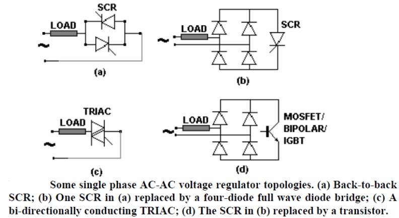
They are called Phase Angle Controlled (PAC) AC-AC converters or AC-AC choppers. The TRIAC based converter may be considered as the basic topology. Being bi-directionally conducting devices, they act on both polarities of the applied voltage.
However, dv/dt re-applied their ratings being poor, they tend to turn-on in the opposite direction just subsequent to their turn-off with an inductive load. The 'Alternistor' was developed with improved features but was not popular. The TRIAC is common only at the low power ranges. The (a) and (b) options are improvements on (c) mostly regarding current handling and turn-off-able current rating.
A transistorised AC-AC regulator is a PWM regulator similar to the DC-DC converters. It also requires a freewheeling path across the inductive load, which has also got to be bi-directional. Consequently, only controlled freewheeling devices can be used.
Operation with resistive loads
The device(s) is triggered at a phase-angle 'α' in each cycle. The current follows the voltage wave shape in each half and extinguishes itself at the zero crossings of the supply voltage. In the two-SCR topology, one SCR is positively biased in each half of the supply voltage. There is no scope for conduction overlap of the devices. A single pulse is sufficient to trigger the controlled devices with a resistive load. In the diode-SCR topology, two diodes are forward biased in each half. The SCR always receives a DC voltage and does not distinguish the polarity of the supply. It is thus always forward biased. The bi-directional TRIAC is also forward biased for both polarities of the supply voltage.
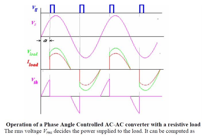
As is evident from the current waveforms, the PAC introduces significant harmonics both into the load and the supply. This is one of the main reasons why such controllers are today not acceptable. The ideal waveform as shown in Fig 26.2 is half wave symmetric. However it is to be achieved by the trigger circuits. The controller in Fig. 26.4 ensures this for the TRIAC based circuit. While the TRIAC has a differing characteristic for the two polarities of biasing with the 32V DIAC - a two terminal device- triggering is effected when the capacitor voltage reaches 32 V. This ensures elimination of DC and even components in the output voltage.
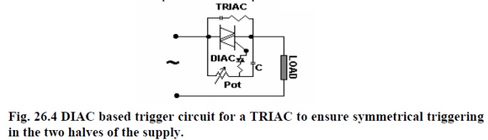
For the SCR based controllers, identical comparators for the two halves of the AC supply, which generates pulses for the two SCRs ensures DC and even harmonic free operation.
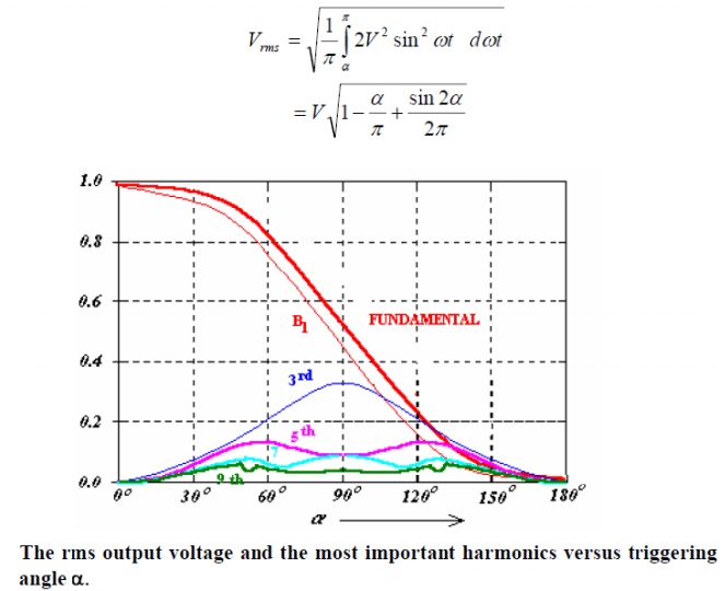
The PAC operates with a resistive load for all values of α ranging from 0 The fundamental current, if can be represented as
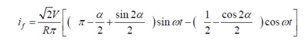
In machine drives it is only the fundamental component, which is useful. However, in resistance heating type of application all harmonics are of no consequence. The corrupted supply current nevertheless is undesirable.
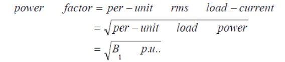
Power Factor
The power factor of a nonlinear deserves a special discussion. Fig. 26.2 shows the supply voltage and the non-sinusoidal load current. The fundamental load/supply current lags the supply voltage by the φ1, 'Fundamental Power Factor' angle. Cosφ1 is also called
the 'Displacement Factor'. However this does not account for the total reactive power drawn by the system. This power factor is inspite of the actual load being resistive! The reactive power is drawn also y the trigger-angle dependent harmonics. Now
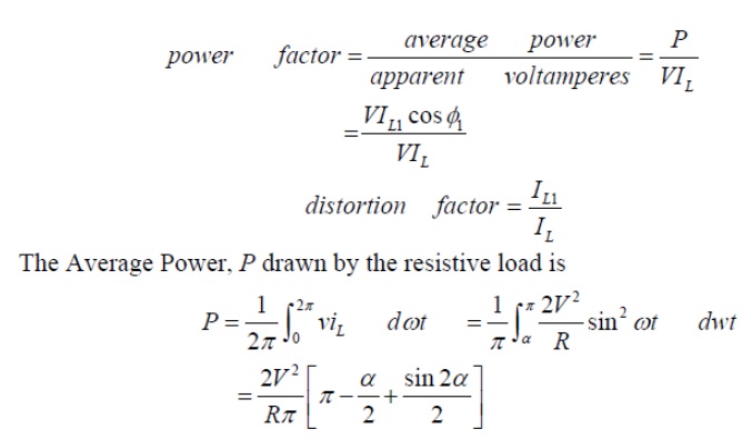
The portion within square brackets in Eq. 26.5 is identical to the first part of the expression within brackets in Eq. 26.1, which is called the Fourier coefficient 'B1
The rms load voltage can also be similarly obtained by integrating between α and π and the result can be combined
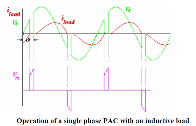
Operation with inductive loads
With inductive loads the operation of the PAC is illustrated in Fig 26.5. The current builds up from zero in each cycle. It quenches not at the zero crossing of the applied voltage as with the resistive load but after that instant. The supply voltage thus continues to be impressed on the load till the load current returns to zero. A single-pulse trigger for the TRIAC 26.1 (c) or the anti-parallel SCR (b) has no effect on the devices if it (or the anti-parallel device) is already in conduction in the reverse direction. The devices would fail to conduct when they are intended to, as they do not have the supply voltage forward biasing them when the trigger pulse arrives. A single pulse trigger will work till the trigger angle α > φ, where φ is the power factor angle of the inductive load. A train of pulses is required here. The output voltage is controllable only between triggering angles φ and 180o .
The load current waveform is further explained in Fig. 26.6. The current is composed of two components. The first is the steady state component of the load current, issand the second, itris the transient component.
With an inductance in the load the distinguishing feature of the load current is that it must always start from zero. However, if the switch could have permanently kept the load connected to the supply the current would have become a sinusoidal one phase shifted from the voltage by the phase angle of the load, φ. This current restricted to the half periods of conduction is called the 'steady-state component' of load current iss. The 'transient component' of load current itr, again in each half cycle, must add up to zero with this issto start from zero. This condition sets the initial value of the transient component to that of the steady state at the instant that the SCR/TRIAC is triggered. Fig. 26.6 illustrates these relations.
When a device is in conduction, the load current is governed by the equation
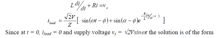
The instant when the load current extinguishes is called the extinction angle β. It can be inferred that there would be no transients in the load current if the devices are triggered at the power factor angle of the load. The load current I that case is perfectly sinusoidal. Three-phase AC Regulators
There are many types of circuits used for the three-phase ac regulators (ac to ac voltage converters), unlike single-phase ones. The three-phase loads (balanced) are connected in star or delta. Two thyristors connected back to back, or a triac, is used for each phase in mo most of the circuits as described. Two circuits are first taken up, both with balanced resistive (R) load.
Related Topics