Chapter: Transmission and Distribution : Structure of Power System
AC and DC Distribution
AC DISTRIBUTION
Now-a-days electrical energy is generated, transmitted and distributed in the form of alternating current. One important reason for the widespread use of alternating current in preference to direct current is the fact that alternating voltage can be conveniently changed in magnitude by means of a transformer. Transformer has made it possible to transmit a.c. power at high voltage and utilise it at a safe potential. High transmission and distribution voltages have greatly reduced the current in the conductors and the resulting line losses.
There is no definite line between transmission and distribution according to voltage or bulk capacity. However, in general, the a.c. distribution system is the electrical system between the step- down substation fed by the transmission system and the consumers’ meters. The a.c. distribution system is classified into
i. primary distribution system and
ii. Secondary distribution system.
i) Primary distribution system.
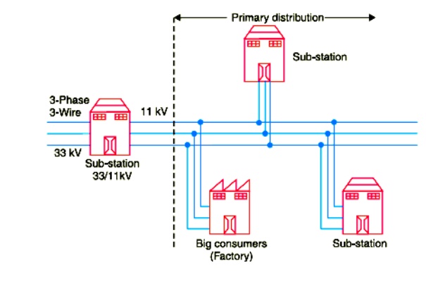
It is that part of a.c. distribution system which operates at voltages somewhat higher than general utilization and handles large blocks of electrical energy than the average low-voltage consumer uses. The voltage used for primary distribution depends upon the amount of power to be conveyed and the distance of the substation required to be fed. The most commonly used primary distribution voltages are 11 kV, 6·6 kV and 3·3 kV.
Due to economic considerations, primary distribution is carried out by 3- phase, 3-wire system Fig. shows a typical primary distribution system Electric power from the generating station is transmitted at high voltage to the substation located in or near the city.
ii) Secondary distribution system
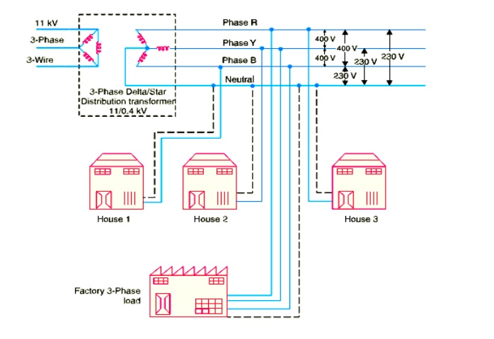
It is that part of a.c. distribution system. The secondary distribution employs 400/230V,3-phase,4wire system. Fig shows a typical secondary distribution system. The primary distribution circuit delivers power to various substations, called distribution sub-stations. The substations are situated near the consumers’ localities and contain step-down transformers. At each distribution substation, the voltage is stepped down to 400Vandpowerisdeliveredby 3-phase,4-wire a.c. system. The voltage between any two phases is 400V and between any phase and neutralize 230V.The single phase domestic loads are connected between any one phase and the neutral, where as 3-phase 400V motor loads are connected across 3- phase lines directly.
D.C. DISTRIBUTION
It is a common knowledge that electric power is almost exclusively generated, transmitted and distributed as a.c. However, for certain applications, d.c. supply is absolutely necessary. For instance, d.c. supply is required for the operation of variable speed machinery (d.c. motors), for electro-chemical work and for congested areas where storage battery reserves are necessary. For this purpose, a.c. power is converted into d.c. power at the substation by using converting machinery e.g., mercury arc rectifiers, rotary converters and motor-generator sets. The d.c. supply from the substation may be obtained in the form of
( i) 2-wire
( ii) 3-wire for distribution.
( i) 2-wire d.c. system.
As the name implies, this system of distribution consists of two wires. One is the outgoing or positive wire and the other is the return or negative wire. The loads such as lamps, motors etc. are connected in parallel between the two wires as shown in Fig. 12.4. This system is never used for transmission purposes due to low efficiency but may be employed for distribution of d.c. power.
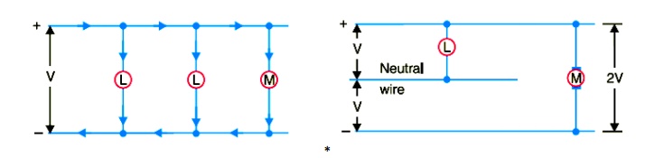
( ii) 3-wire d.c. system.
It consists of two outers and a middle or neutral wire which is earthed at the substation. The voltage between the outers is twice the voltage between either outer and neutral wire as shown in Fig. 12.5. The principal advantage of this system is that it makes available two voltages at the consumer terminals viz., V between any outer and the neutral and 2V between the outers. Loads requiring high voltage ( e.g., motors) are connected across the outers, whereas lamps and heating circuits requiring less voltage are connected between either outer and the neutral. The methods of obtaining 3-wire system are discussed in the following article.
Related Topics