Chapter: Environmental Engineering : Water Treatment
Water Tretment: Sodium Zeolite Softening
WATER TRETMENT: SODIUM ZEOLITE SOFTENING
Sodium zeolite
softening is the most widely applied use of ion exchange. In zeolite softening,
water containing scale-forming ions, such as calcium and magnesium, passes
through a resin bed containing SAC resin in the sodium form. In the resin, the
hardness ions are exchanged with the sodium, and the sodium diffuses into the
bulk water solution. The hardness-free water, termed soft water, can then be
used for low to medium pressure boiler feedwater, reverse osmosis system
makeup, some chemical processes, and commercial applications, such as
laundries.
Principles of Zeolite
Softening
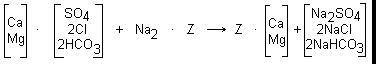
The
removal of hardness from water by a zeolite softening process is described by
the following reaction:
Water
from a properly operated zeolite softener is nearly free from detectable
hardness. How-ever, some small amounts of hardness, known as leakage, are
present in the treated water. The level of hardness leakage is dependent on the
hardness and sodium level in the influent water and the amount of salt used for
regeneration.
Figure
8-5 is a typical profile of effluent hardness from a zeolite softener during a
service cycle. After final rinse, the softener produces a low, nearly constant
level of hardness until the ion exchange resin nears exhaustion. At exhaustion,
the effluent hardness increases sharply, and regeneration is required.
As
illustrated by the softening reactions, SAC resin readily accepts calcium and
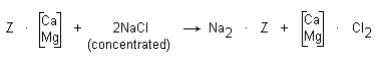
magnesium ions in exchange for sodium ions. When exhausted resin is
regenerated, a high concentration of sodium ions is applied to the resin to
replace calcium and magnesium. The resin is treated with a 10% sodium chloride
solution, and regeneration proceeds according to the following equation:
During
regeneration, a large excess of regenerant (approximately 3 times the amount of
calcium and magnesium in the resin) is used. The eluted hardness is removed
from the softening unit in the waste brine and by rinsing.
After
regeneration, small residual amounts of hardness remain in the resin. If resin
is allowed to sit in a stagnant vessel of water, some hardness will diffuse
into the bulk water. Therefore, at the initiation of flow, the water effluent
from a zeolite softener can contain hardness even if it has been regenerated
recently. After a few minutes of flow, the hardness is rinsed from the
softener, and the treated water is soft.
The
duration of a service cycle depends on the rate of softener flow, the hardness
level in the water, and the amount of salt used for regeneration. Table 8-1
shows the effect of regenerant level on the softening capacity of a gelular
strong cation resin. Note that the capacity of the resin increases as the
regenerant dosage increases, but the increase is not proportional. The
regeneration is less efficient at the higher regenerant levels. Therefore,
softener operating costs increase as the regenerant level increases. As shown
by the data in Table 8-1, a 150% increase in regenerant salt provides only a
67% increase in operating capacity.
Table 8-1. Effect of
regenerant salt level on strong acid cation resin softening capacity.
Salt (lb/ft3) Capacity (gr/ft3)
6 18,000
8 20,000
10 24,000
15 30,000
Equipment
The
equipment used for sodium zeolite softening consists of a softener exchange
vessel, control valves and piping, and a system for brining, or regenerating,
the resin. Usually, the softener tank is a vertical steel pressure vessel with
dished heads as shown in Figure 8-6. Major features of the softening vessel
include an inlet distribution system, free-board space, a regenerant
distribution system, ion exchange resin, and a resin-retaining underdrain
collection system.
The
inlet distribution system is usually located at the top of the tank. The inlet
system provides even distribution of influent water. This prevents the water
from hollowing out flow channels in the resin bed, which would reduce system
capacity and effluent quality. The inlet system also acts as a collector for
backwash water.
The
inlet distributor consists of a central header/hub with distributing
laterals/radials or simple baffle plates, which direct the flow of water evenly
over the resin bed. If water is not prevented from flowing directly onto the
bed or tank walls, channeling will result.
The
volume between the inlet distributor and the top of the resin bed is called the
free-board space. The free-board allows for the expansion of the resin during the
backwash portion of the regeneration without loss of resin. It should be a
minimum of 50% of the resin volume (80% preferred).
The regenerant distributor is usually a
header-lateral system that evenly distributes the regenerant brine during
regeneration. The location of the distributor, 6 in. above the top of the resin
bed, prevents the dilution of regenerant by water in the free-board space. It
also reduces water and time requirements for displacement and fast rinse. The
regenerant distributor should be secured to the tank structure to prevent
breakage and subsequent channeling of the regenerant.
Water is softened by the bed of strong acid cation
exchange resin in the sodium form. The quantity of resin required depends on
the water flow, total hardness, and time desired between regeneration cycles. A
minimum bed depth of 24 in. is recommended for all systems.
The underdrain system, located at the bottom of the
vessel, retains ion exchange resin in the tank, evenly collects the service
flow, and evenly distributes the backwash flow. Uneven collection of water in
service or uneven distribution of the backwash water can result in channeling,
resin fouling, or resin loss.
Although several underdrain designs are used, there
are two primary types-subfill and resin-retaining. A subfill system consists of
multiple layers of support media (such as graded gravel or anthracite) which
support the resin, and a collection system incorporating drilled pipes or
subfill strainers. As long as the support layers remain intact, the resin will
remain in place. If the supporting media becomes disturbed, usually due to
improper backwash, the resin can move through the disrupted layers and exit the
vessel. A resin-retaining collector, such as a screened lateral or profile wire
strainer, is more expensive than a subfill system but protects against resin
loss.
The main valve and piping system directs the flow of
water and regenerant to the proper locations. The valve system consists of a
valve nest or a single multiport valve. A valve nest includes six main valves:
service inlet and outlet, backwash inlet and outlet, regenerant inlet, and
regenerant/rinse drain. The valves may be operated manually, or automatically
controlled by air, electrical impulse, or water pressure. In some systems, a
single multiport valve is used in place of the valve nest. As the valve rotates
through a series of fixed positions, ports in the valve direct flow in the same
manner as a valve nest. Multiport valves can eliminate operational errors
caused by opening of the incorrect valve but must be properly maintained to
avoid leaks through the port seals.
The brining system consists of salt dissolving/brine
measuring equipment, and dilution control equipment to provide the desired
regenerant strength. The dissolving/measuring equipment is designed to provide
the correct amount of concentrated brine (approximately 26% NaCl) for each
regeneration, without allowing any undissolved salt into the resin. Most
systems use a float-operated valve to control the fill and draw-down of the
supply tank, thereby controlling the amount of salt used in the regeneration.
Usually, the concentrated brine is removed from the tank by means of an eductor
system, which also dilutes the brine to the optimum regenerant strength (8-10%
NaCl). The brine can also be pumped from the concentrated salt tank and mixed
with dilution water to provide the desired regenerant strength.
Softener
Operation
A sodium zeolite softener operates through two basic
cycles: the service cycle, which produces soft water for use, and the
regeneration cycle, which restores resin capacity at exhaustion.
In the service cycle, water enters the softener
through the inlet distribution system and flows through the bed. The hardness
ions diffuse into the resin and exchange with sodium ions, which return to the
bulk water. Soft water is collected in the underdrain system and discharged.
Service water flow to the softener should be as constant as possible to prevent
sudden surges and frequent on-off operation.
Due to resin requirements and vessel designs, the
softening operation is most efficient when a service flow rate between 6 and 12
gpm per square foot of resin surface area is maintained. Most equipment is
designed to operate in this range, but some special designs utilize a deep
resin bed to permit operation at 15-20 gpm/ft�. Continuous operation above the
manufacturer's suggested limits can lead to bed compaction, channeling,
premature hardness breakthrough, and hardness leakage. Operating well below the
manufacturer's recommended flow rates can also negatively affect softener
performance. At low flow rates, the water is not sufficiently distributed, and
the optimum resin-water contact cannot take place.
When a softener is exhausted, the resin must be
regenerated. Monitoring of the effluent hardness reveals resin exhaustion. When
hardness increases, the unit is exhausted. Automatic monitors pro-vide a more
constant indication of the condition of the softener than periodic operator
sampling and testing, but require frequent maintenance to ensure accuracy. Many
facilities regenerate softeners before exhaustion, based on a predetermined
time period or number of gallons processed.
Most softening systems consist of more than one
softener. They are often operated so that one softener is in regeneration or
standby while the other units are in service. This ensures an uninterrupted
flow of soft water. Prior to placing a standby softener into service, the unit
should be rinsed to remove any hardness that has entered the water during the
standing time.
Softener
Regeneration
The regeneration cycle of a sodium zeolite softener
consists of four steps: backwash, regeneration (brining), displacement (slow
rinse), and fast rinse.
Backwash. During the service cycle, the downward
flow of water causes suspended material to accumulate on the resin bed. Resin
is an excellent filter and can trap particulate matter that has passed through
upstream filtration equipment. The backwash step removes accumulated material
and reclassifies the resin bed. In the backwash step, water flows from the
underdrain distributor up through the resin bed and out the service distributor
to waste. The upward flow lifts and expands the resin, allowing for removal of
particulate material and resin fines and the classification of the resin. Resin
classification brings the smaller beads to the top of the unit while the larger
beads settle to the bottom. This enhances the distribution of the regenerant
chemical and service water.
Backwashing should continue for a minimum of 10 min
or until effluent from the backwash outlet is clear. The backwash flow should
be sufficient to expand the resin bed volume by 50% or more, depending on the
available free-board. Insufficient backwash can lead to bed fouling and
channeling. Excessive backwash flow rates result in the loss of resin. Backwash
flow rates usually vary between 4-8 (ambient temperature) and 12-15 (hot
service) gpm per square foot of bed area, but each manufacturer's
recommendation should be followed. The ability of water to expand the resin is
greatly affected by temperature. Less flow is required to expand the bed with
cold water than with warm water. Resin bed expansion should be checked
regularly and the flow rate adjusted as needed to maintain proper bed
expansion.
Usually,
the backwash water
is filtered raw
water. Water leaving
the backwash outlet
is unchanged in chemistry but can contain suspended solids. In order to
conserve water, the backwash effluent can be returned to the clarifier or
filter influent for treatment.
Regeneration (Brining). After backwash, regenerant
brine is applied. The brine stream enters the unit through the regenerant
distributor and flows down through the resin bed at a slow rate (usually
between 0.5 and 1 gpm per square foot of resin). Brine flow is collected
through the underdrain and sent to waste. The slow flow rate increases contact
between the brine and resin. To achieve optimum efficiency from the brine, the
solution strength should be 10% during brine introduction.
Displacement (Slow Rinse). Following the
introduction of regenerant brine, a slow flow of water continues through the
regenerant distribution system. This water flow displaces the regenerant
through the bed at the desired flow rate. The displacement step completes the
regeneration of the resin by ensuring proper contact of the regenerant with the
bottom of the resin bed. The flow rate for the displacement water is usually
the same rate used for the dilution of the concentrated brine. The duration of
the displacement step should be sufficient to allow for approximately one resin
bed volume of water to pass through the unit. This provides a "plug"
of displacement water which gradually moves the brine completely through the
bed.
Fast Rinse. After completion of the displacement
rinse, water is introduced through the inlet distributor at a high flow rate.
This rinse water removes the remaining brine as well as any residual hardness
from the resin bed. The fast rinse flow rate is normally between 1.5 and 2 gpm
per square foot of resin. Sometimes it is deter-mined by the service rate for
the softener.
Initially, the rinse
effluent contains large amounts of hardness and sodium chloride. Usually,
hardness is rinsed from the softener before excess sodium chloride. In many
operations, the softener can be returned to service as soon as the hardness
reaches a predetermined level, but some uses require rinsing until the effluent
chlorides or conductivity are near influent levels. An effective fast rinse is
important to ensure high effluent quality during the service run. If the
softener has been in standby following a regeneration, a second fast rinse,
known as a service rinse, can be used to remove any hardness that has entered
the water during standby.
Related Topics