Chapter: Transmission and Distribution : Modelling and Performance of Transmission Lines
Voltage Control - Introduction
VOLTAGE CONTROL - INTRODUCTION
In a
modern power system, electrical energy from the generating station is delivered
to the ultimate consumers through a network of transmission and distribution.
For satisfactory operation of motors, lamps and other loads, it is desirable
that consumers are supplied with substantially constant voltage. Too wide
variations of voltage may cause erratic operation or even malfunctioning of
consumers’ appliances. To safe- guard the interest of the consumers, the
government has enacted a law in this regard. The statutory limit of voltage
variation is ± 6% of declared voltage at consumers’ terminals. The principal
cause of voltage variation at consumer’s premises is the change in load on the
supply system. When the load on the system increases, the voltage at the
consumer’s terminals falls due to the increased voltage drop in
( i) alternator synchronous impedance
( ii) transmission line
( iii) transformer impedance
( iv) feeders and Condenser
(v) Distributors.
The
reverse would happen should the load on the system decrease. These voltage
variations are undesirable and must be kept within the prescribed limits ( i.e.
± 6% of the declared voltage). This is achieved by installing voltage
regulating equipment at suitable places in the Voltage Control power system.
The purpose of this chapter is to deal with important voltage control equipment
and its increasing utility in this fast developing power system.
1. IMPORTANCE OF VOLTAGE CONTROL
When the
load on the supply system changes, the voltage at the consumer’s terminals also
changes.
The
variations of voltage at the consumer’s terminals are undesirable and must be
kept within prescribed limits for the following reasons :
( i) In case of lighting load, the
lamp characteristics are very sensitive to changes of voltage.
For
instance, if the supply voltage to an incandescent lamp decreases by 6% of
rated value, then illuminating power may decrease by 20%. On the other hand, if
the supply voltage is 6% above the rated value, the life of the lamp may be
reduced by 50% due to rapid deterio-ration of the filament.
( ii) In case of power load consisting
of induction motors, the voltage variations may cause erratic operation. If the supply voltage is above the
normal, the motor may operate with a saturated magnetic circuit, with
consequent large magnetising current, heating and low power factor. On the
other hand, if the voltage is too low, it will reduce the starting torque of the
motor considerably.
( iii) Too wide variations of voltage
cause excessive heating of distribution transformers. This may reduce their ratings to a considerable extent.
It is
clear from the above discussion that voltage variations in a power system must be
kept to minimum level in order to deliver good service to the consumers. With
the trend towards larger and larger interconnected system, it has become
necessary to employ appropriate methods of voltage control.
2. LOCATION OF VOLTAGE CONTROL
EQUIPMENT
In a
modern power system, there are several elements between the generating station
and the consumers. The voltage control equipment is used at more than one point
in the system for two reasons.
Firstly,
the power network is very extensive and there is a considerable voltage drop in
transmission and distribution systems. Secondly, the various circuits of the
power system have dissimilar load characteristics. For these reasons , it is
necessary to provide individual means of voltage control for each circuit or
group of circuits. In practice, voltage control equipment is used at :
( i) generating stations
( ii) transformer
stations
(iii) the feeders if the drop exceeds the permissible limits 15.3 Methods of Voltage Control
There are
several methods of voltage control. In each method, the system voltage is
changed in accordance with the load to obtain a fairly constant voltage at the
consumer’s end of the system. The following are the methods of voltage control
in an *a.c. power system:
( i) By excitation control
( ii) By using tap changing transformers
( iii) Auto-transformer tap changing
( iv) Booster transformers
( v) Induction regulators
( vi) By synchronous condenser
Method (
i) is used at the generating station only whereas methods ( ii) to ( v) can be
used for transmission as well as primary
distribution systems. However, methods ( vi) is reserved for the voltage
control of a transmission line. We shall discuss each method separately in the
next sections.
1.Excitation Control
When the
load on the supply system changes, the terminal voltage of the alternator also
varies due to the changed voltage drop in the synchronous reactance of the
armature. The voltage of the alternator can be kept constant by changing the
*field current of the alternator in accordance with the load. This is known as
excitation control method. The excitation of alternator can be controlled by
the use of automatic or hand operated regulator acting in the field circuit of
the alternator. The first method is preferred in modern practice. There are two
main types of automatic voltage regulators viz.
( i) Tirril Regulator
( ii) Brown-Boveri Regulator
These
regulators are based on the “overshooting the mark †principle” to enable them
to respond quickly to the rapid fluctuations of load. When the load on the
alternator increases, the regulator produces an increase in excitation more
than is ultimately necessary. Before the voltage has the time to increase to
the value corresponding to the increased excitation, the regulator reduces the
excitation to the proper value.
i)Tirril Regulator
In this
type of regulator, a fixed resistance is cut in and cut out of the exciter
field circuit of the alternator. This is achieved by rapidly opening and
closing a shunt circuit across the exciter rheostat.
For this
reason, it is also known as vibrating type voltage regulator.
Construction
Fig.
shows the essential parts of a Tirril voltage regulator. A rheostat R is
provided in the exciter circuit and its value is set to give the required excitation.
This rheostat is put in and out of the exciter circuit by the regulator, thus
varying the exciter voltage to maintain the desired voltage of the alternator.
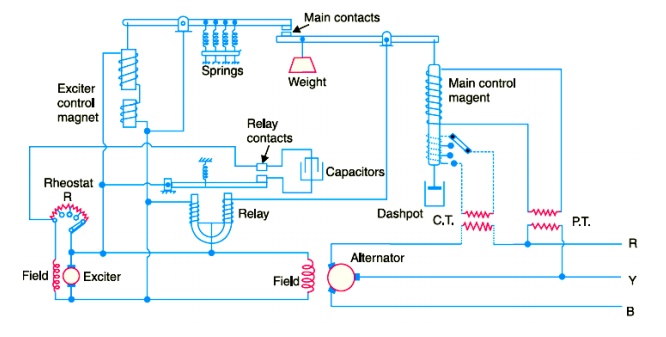
( i) Main contact.
There are
two levers at the top which carry the main contacts at the facing ends. The
left-hand lever is controlled by the exciter magnet whereas the right hand
lever is controlled by an a.c. magnet known as main control magnet.
( ii) Exciter magnet.
This
magnet is of the ordinary solenoid type and is connected across the exciter
mains. Its exciting current is, therefore, proportional to the exciter voltage.
The counter balancing force for the exciter magnet is provided by four coil
springs.
( iii) A. C. magnet.
It is
also of solenoid type and is energised from a.c. bus-bars. It carries series as
well as shunt excitation. This magnet is so adjusted that with normal load and
voltage at the alternator, the pulls of the two coils are equal and opposite,
thus keeping the right-hand lever in the horizontal position.
( iv) Differential relay.
It
essentially consists of a U-shaped relay magnet which operates the relay
contacts. The relay magnet has two identical windings wound differentially on
both the limbs. These windings are connected across the exciter mains–the left
hand one permanently while the right hand one has its circuit completed only
when the main contacts are closed. The relay contacts are arranged to shunt the
exciter-field rheostat R. A capacitor is provided across the relay contacts to
reduce the sparking at the time the relay contacts are opened.
Operation
The two
control magnets ( i.e. exciter magnet and a.c. magnet) are so adjusted that
with normal load and voltage at the alternator, their pulls are equal, thus
keeping the main contacts open. In this position of main contacts, the relay
magnet remains energised and pulls down the armature carrying one relay
contact. Consequently, relay contacts remain open and the exciter field
rheostat is in the field circuit.
When the
load on the alternator increases, its terminal voltage tends to fall. This
causes the series excitation to predominate and the a.c. magnet pulls down the
right-hand lever to close the main contacts. Consequently, the relay magnet is
*de-energised and releases the armature carrying the relay contact. The relay
contacts are closed and the rheostat R in the field circuit is short circuited.
This
increases the exciter-voltage and hence the excitation of the alternator. The
increased excitation causes the alternator voltage to rise quickly. At the same
time, the excitation of the exciter magnet is increased due to the increase in
exciter voltage. Therefore, the left-hand lever is pulled down, opening the
main contacts, energising the relay magnet and putting the rheostat R again in
the field circuit before the alternator voltage has time to increase too far.
The reverse would happen should the load on the alternator decrease.
It is
worthwhile to mention here that exciter voltage is controlled by the rapid
opening and closing of the relay contacts. As the regulator is worked on the
overshooting the mark principle, therefore, the terminal voltage does not
remain absolutely constant but oscillates between the maximum and minimum
values. In fact, the regulator is so quick acting that voltage variations never
exceed ± 1%.
ii)Brown-Boveri Regulator
In this
type of regulator, exciter field rheostat is varied continuously or in small
steps instead of being first completely cut in and then completely cut out as
in Tirril regulator. For this purpose, a regulating resistance is connected in
series with the field circuit of the exciter. Fluctuations in the alternator
voltage are detected by a control device which actuates a motor. The motor
drives the regulating rheostat and cuts out or cuts in some resistance from the
rheostat, thus changing the exciter and hence the alternator voltage.
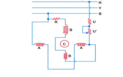
Construction
Fig.
shows the schematic diagram of a Brown-Boveri voltage regulator. It also works
on the “overshooting the mark principle” and has the following four important
parts :
( i) Control system
The
control system is built on the principle of induction motor. It consists of two
windings A and B on an annular core of laminated sheet steel. The winding A is
excited from two of the generator terminals through resistances U and U′ while
a resistance R is inserted in the circuit of winding B. The ratio of resistance
to reactance of the two windings are suitably adjusted so as to create a phase
difference of currents in the two windings. Due to the phase difference of
currents in the two windings, rotating magnetic field is set up. This produces
electromagnetic torque on the thin aluminium drum C carried by steel spindle ;
the latter being supported at both ends by jewel bearings. The torque on drum C
varies with the terminal voltage of the alternator. The variable resistance U’
can also vary the torque on the drum.
If the
resistance is increased, the torque is decreased and vice-versa. Therefore, the
variable resistance U′ provides a means by which the regulator may be set to
operate at the desired voltage.
( ii) Mechanical control torque
The
electric torque produced by the current in the split phase winding is opposed
by a combination of two springs (main spring and auxiliary spring) which
produce a constant mechanical torque irrespective of the position of the drum.
Under steady deflected state, mechanical torque is equal and opposite to the
electric torque.
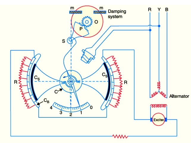
( iii) Operating system
It
consists of a field rheostat with contact device. The rheostat consists of a
pair of resistance elements connected to the stationary contact blocks CB
. These two resistance sectors R are connected in series with each other and
then in series with the field circuit of the exciter.
On the
inside surface of the contact blocks roll the contact sectors Cs .
When the
terminal voltage of the alternator changes, the electric torque acts on the
drum. This causes the contact sectors to roll over the contact blocks, cutting
in or cutting out rheostat resistance in the exciter field circuit.
( iv) Damping torque
The
regulator is made stable by damping mechanism which consists of an aluminium
disc O rotating between two permanent magnets m. The disc is geared to the rack
of an aluminium sector P and is fastened to the aluminium drum C by means of a
flexible spring S acting as the recall spring. If there is a change in the alternator
voltage, the eddy currents induced in the disc O produce the necessary damping
torque to resist quick response of the moving system.
Operation
Suppose
that resistances U and U′ are so adjusted that terminal voltage of the
alternator is normal at position 1. In this position, the electrical torque is
counterbalanced by the mechanical torque and the moving system is in
equilibrium. It is assumed that electrical torque rotates the shaft in a
clockwise direction.
Now
imagine that the terminal voltage of the alternator rises due to decrease in
load on the supply system. The increase in the alternator voltage will cause an
increase in electrical torque which becomes greater than the mechanical torque.
This causes the drum to rotate in clockwise direction, say to position 3. As a
result, more resistance is inserted in the exciter circuit, thereby decreasing
the field current and hence the terminal voltage of the alternator. Meanwhile,
the recall spring S is tightened and provides a counter torque forcing the
contact roller back to position 2 which is the equilibrium position. The
damping system prevents the oscillations of the system about the equilibrium
position.
2.Tap-Changing Transformers
The
excitation control method is satisfactory only for relatively short lines.
However, it is *not suitable for long lines as the voltage at the alternator
terminals will have to be varied too much in order that the voltage at the far
end of the line may be constant. Under such situations, the problem of voltage
control can be solved by employing other methods. One important method is to
use tap-changing transformer and is commonly employed where main transformer is
necessary. In this method, a number of tappings are provided on the secondary
of the transformer. The voltage drop in the line is supplied by changing the
secondary e.m.f. of the transformer through the adjustment of its number of
turns.
( i) Off load tap-changing transformer.
Fig.
shows the arrangement where a number of tappings have been provided on the
sec-ondary. As the position of the tap is varied, the effective number of
secondary turns is varied and hence the output voltage of the secondary can be
changed. Thus referring to Fig.
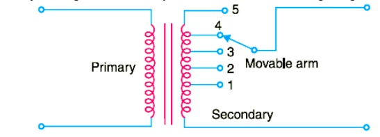
when the
movable arm makes contact with stud 1, the secondary voltage is minimum and
when with stud 5, it is maximum. During the period of light load, the voltage
across the primary is not much below the alternator voltage and the movable arm
is placed on stud 1. When the load increases, the voltage across the primary
drops, but the secondary voltage can be kept at the previous value by placing
the movable arm on to a higher stud. Whenever a tapping is to be changed in
this type of transformer, the load is kept off and hence the name off load
tap-changing transformer. The principal disadvantage of the circuit arrangement
shown in Fig. is that it cannot be used for tap-changing on load. Suppose for a
moment that tapping is changed from position 1 to position 2 when the
transformer is supplying load. If contact with stud 1 is broken before contact
with stud 2 is made, there is break in the circuit and arcing results. On the
other hand, if contact with stud 2 is made before contact with stud 1 is
broken, the coils connected between these two tappings are short-circuited and
carry damaging heavy currents. For this reason, the above circuit arrangement
cannot be used for tap-changing on load.
( ii) On-load tap-changing transformer
In supply
system, tap-changing has normally to be performed on load so that there is no
interruption to supply. Fig shows diagrammatically one type of on-load
tap-changing transformer. The secondary consists of two equal parallel windings
which have similar tappings 1 a ...... 5 a and 1 b ......... 5 b. In the normal
working conditions, switches a, b and tappings with the same number remain
closed and each secondary winding carries one-half of the total current.
Referring to Fig.
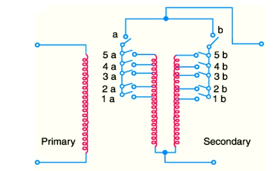
the
secondary voltage will be maximum when switches a, b and 5 a, 5 b are closed.
However, the secondary voltage will be minimum when switches a, b and 1 a, 1 b
are closed. Suppose that the transformer is working with tapping position at 4
a, 4 b and it is desired to alter its position to 5 a, 5 b. For this purpose,
one of the switches a and b, say a, is opened. This takes the secondary winding
controlled by switch a out of the circuit. Now, the secondary winding
controlled by switch b carries the total current which is twice its rated
capacity. Then the tapping on the disconnected winding is changed to 5 a and
switch a is closed. After this, switch b is opened to disconnect its winding,
tapping position on this winding is changed to 5 b and then switch b is closed.
In this way, tapping position is changed without interrupting the supply.
This method has the following disadvantages:
( i) During switching, the impedance
of transformer is increased and there will be a voltage surge.
( ii) There are twice as many tappings
as the voltage steps.
3.Auto-Transformer Tap-changing
Fig.
shows diagrammatically auto-transformer tap changing. Here, a mid-tapped
auto-transformer or reactor is used. One of the lines is connected to its
mid-tapping. One end, say a of this transformer is connected to a series of
switches across the odd tappings and the other end b is connected to switches
across even tappings. A short-circuiting switch S is connected across the
auto-transformer and remains in the closed position under normal operation. In
the normal operation, there is *no inductive voltage drop across the
auto-transformer. Referring to Fig, it is clear that with switch 5 closed,
minimum secondary turns are in the circuit and hence the output voltage will be
the lowest. On the other hand, the output voltage will be maximum when switch 1
is closed.
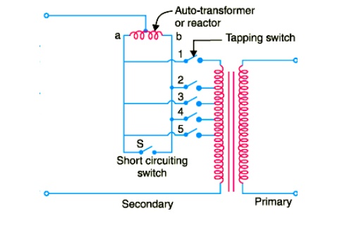
Suppose
now it is desired to alter the tapping point from position 5 to position 4 in
order to raise the output voltage. For this purpose, short-circuiting switch S
is opened, switch 4 is closed, then switch 5 is opened and finally
short-circuiting switch is closed. In this way, tapping can be changed without
interrupting the supply.
It is
worthwhile to describe the electrical phenomenon occurring during the tap
changing. When the short-circuiting switch is opened, the load current flows
through one-half of the reactor coil so that there is a voltage drop across the
reactor. When switch 4 is closed, the turns between points 4 and 5 are
connected through the whole reactor winding. A circulating current flows
through this local circuit but it is limited to a low value due to high
reactance of the reactor.
4.Booster Transformer
Sometimes
it is desired to control the voltage of a transmission line at a point far away
from the main transformer. This can be conveniently achieved by the use of a
booster transformer as shown in Fig.
The
secondary of the booster transformer is connected in series with the line whose
voltage is to be controlled. The primary of this transformer is supplied from a
regulating transformer *fitted with on-load tap-changing gear. The booster
transformer is connected in such a way that its secondary injects a voltage in
phase with the line voltage.
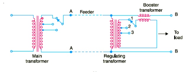
The
voltage at AA is maintained constant by tap-changing gear in the main
transformer. However, there may be considerable voltage drop between AA and BB
due to fairly long feeder and tapping of loads. The voltage at BB is controlled
by the use of regulating transformer and booster transformer. By changing the
tapping on the regulating transformer, the magnitude of the voltage injected
into the line can be varied. This permits to keep the voltage at BB to the
de-sired value. This method of voltage control has three disadvantages. Firstly,
it is more expensive than the on-load tap-changing transformer. Secondly, it is
less efficient owing to losses in the booster and thirdly more floor space is
required. Fig. shows a three-phase booster transformer.
6.Induction Regulators
An
induction regulator is essentially a constant voltage transformer, one winding
of which can be moved w.r.t. the other, thereby obtaining a variable secondary
voltage. The primary winding is connected across the supply while the secondary
winding is connected in series with the line whose voltage is to be controlled.
When the position of one winding is changed w.r.t. the other, the secondary
voltage injected into the line also changes. There are two types of induction
regulators viz. single phase and 3-phase.
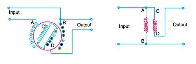
( i) Single-phase induction
regulator.
A single
phase induction regulator is illustrated in Fig. In construction, it is similar
to a single phase induction motor except that the rotor is not allowed to
rotate continuously but can be adjusted in any position either manually or by a
small motor. The primary winding A B is wound on the *stator and is connected
across the supply line. The secondary winding CD is wound on the rotor and is
connected in series with the line whose voltage is to be controlled.
The
primary exciting current produces an alternating flux that induces an
alternating voltage in the secondary winding CD. The magnitude of voltage
induced in the secondary depends upon its position w.r.t. the primary winding.
By adjusting the rotor to a suitable position, the secondary voltage can be
varied from a maximum positive to a maximum negative value. In this way, the
regulator can add or subtract from the circuit voltage according to the
relative positions of the two windings.
Owing to
their greater flexibility, single phase regulators are frequently used for
voltage control of distribution primary feeders.
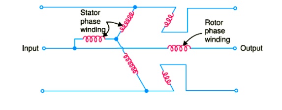
( ii) Three-phase induction
regulator
In
construction, a 3-phase induction regulator is similar to a 3-phase induction
motor with wound rotor except that the rotor is not allowed to rotate
continuously but can be held in any position by means of a worm gear. The
primary windings either in star or delta are wound on the stator and are
connected across the supply. The secondary windings are wound on the rotor and
the six terminals are brought out since these windings are to be connected in
series with the line whose voltage is to be controlled.
When poly
phase currents flow through the primary windings, a rotating field is set up
which induces an e.m.f. in each has of rotor winding. As the rotor is turned,
the magnitude of the rotating flux is not changed; hence the rotor e.m.f. per
phase remains constant. However, the variation of the position of the rotor
will affect the phase of the rotor e.m.f. w.r.t. the applied voltage as shown
in Fig.
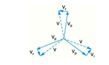
The input
primary voltage per phase is Vp and the boost introduced by the regulator is Vr
. The output voltage V is the vector sum of Vp and Vr . Three phase p induction
regulators are used to regulate the voltage of feeders and in connection with
high voltage oil testing transformers.
6.Voltage Control by Synchronous Condenser
The
voltage at the receiving end of a transmission line can be controlled by
installing specially designed synchronous motors called *synchronous condensers
at the receiving end of the line. The synchronous condenser supplies watt less
leading kVA to the line depending upon the excitation of the motor. This watt
less leading kVA partly or fully cancels the watt less lagging kVA of the line,
thus controlling the voltage drop in the line. In this way, voltage at the
receiving end of a transmission line can be kept constant as the load on the
system changes.
For
simplicity, consider a short transmission line where the effects of capacitance
are neglected. Therefore, the line has only resistance and inductance. Let V1
and V2 be the per phase sending end and receiving end voltages
respectively. Let I2 be the load current at a lagging power factor
of cos φ2 .
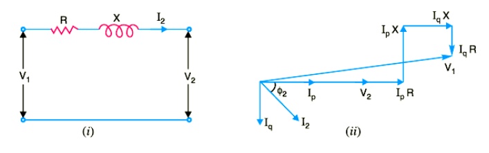
( i) Without synchronous condenser.
Fig. ( i)
shows the transmission line with resistance R and inductive reactance X per
phase. The load current I can be resolved into two 2 rectangular components viz
I in phase with V and I at right angles to V Each component will produce
resistive and reactive drops ; the resistive drops being in phase with and the
reactive drops in quadrature leading with the corresponding currents. The
vector addition of these voltage drops to V gives the sending end voltage V
( ii) With synchronous condenser
Now
suppose that a synchronous condenser taking a leading current * *I is connected
at the receiving end of the line. The vector diagram of the circuit becomes as
shown in Fig. Note that since I and I are in direct opposition and that I must
be greater than I , the four drops due to these two currents simplify to :
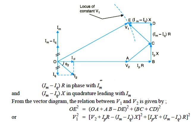
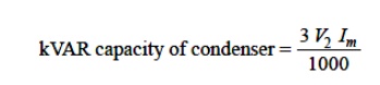
From this
equation, the value of Im can
be calculated to obtain any desired ratio of V1 / V2 for a
Related Topics