Chapter: Special Electrical Machines : Synchronous Reluctance Motors
Vernier Motors
VERNIER MOTORS
A Vernier
motor is an unexcited (or reluctance Type) inductor synchronous motor. It is
also named because it operates on the principle of a vernier. The peculiar
feature of this kind of motor is that a small displacement of the rotor
produces a large displacement of the axes of maximum and minimum permeance.
When a rotating magnetic field is introduced in the air gap of the machine,
rotor will rotate slowly and at a definite fraction of the speed of the
rotating field.
This
rotating field can be produced either by feeding poly phase current to the
stator winding or by exciting the stator coil groups in sequence. AS the rotor
speed steps down from the speed of the rotating field, the motor torque steps
up. A vernier motor works as an electric gearing. This kind of motor is
attractive in applications which require low speed and high torque and where
mechanical gearing is undesirable.
1. Principle of operation
The
stator of a vernier motor has slots and a distributed winding just like the
stator of an ordinary poly phase induction motor. The rotor is a slotted iron
core without winding. A 2 – pole machine with 12 stator slots and 10 rotor
slots.
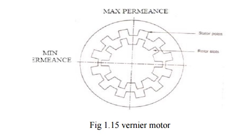
The
stator and rotor teeth are facing each other in the vertical axis. The stator
teeth are facing rotor slots in the horizontal axis. At this position
therefore, the maximum permeance is along the vertical axis and the minimum
permeance is along the horizontal axis. When then rotor is rotated one half of
its slot pitch, the rotor slots will face stator teeth in the vertical axis.
The rotor and stator teeth will face each other in the horizontal axis. The
axis of maximum permeance is now horizontal and the axis of minimum permeance
is now vertical. Thus the rotor movement of one –half rotor slot pitch results
in a 90 degree displacement of the permeance axes.
Suppose
that a magnetic field is rotating in the machine. Whenever the rotating field rotates
90 degrees, the rotor will rotate one half of its slot pitch. When the rotating
field completes one revolution, the rotor will rotate through an angle
corresponding to two rotor slot pitches.
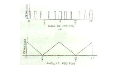
2. Air – Gap permeance
Distribution
The
fluxes in the air gap are assumed all in the radial direction. The permeance of
air space between stator and rotor at any location is inversely proportional to
the radial length of air space at that location. The stator and rotor slot
depth are much larger in comparison with air gap length, the permeance of
airspace can be considered as zero, where stator tooth surface is facing rotor
tooth surface. The width of rectangular blocks is the widths of overlap between
the stator and the rotor teeth. These widths of overlap vary linearly from a
maximum and back to a minimum. The area of overlap is reduced a constant amount
for each successive stator tooth until a minimum is reached.
The
permeance distribution curve is not convenient to use because it cannot be
represented by simple mathematical function. When the rotor rotates, this
permanence wave rotates at a much faster speed. Five times the rotor speed for
the machine. The axes at which maximum and minimum permeance occur are tge
direct and quadrature axes respectively of the vernier motor.
3. Design of Vernier Motor
In a poly
phase reluctance motor the rotor has the same number of poles as the stator
mmfwave.Similarly in a vernier motor the air gap permeance wave should have the
same number of poles as the stator mmf wave. The number of stator and rotor
slots has the following relation
N1 = N2 ±
P
Where
N1 –
Number of Stator Slots
N2 –
Number of Rotor Slots
P –
Number of poles of the rotating magnetic field.
When the
rotor rotates through an angle corresponding to one rotor slot pitch, the
permeance wave rotates through an angle corresponding to one pole pitch. The
pole pitch of the permeance wave is the same as the pole pitch of the stator
mmf wave, because they have the same number of poles. Also in a reluctance
machine, the speed of the permeance wave is the speed of rotating mmf.
Therefore,
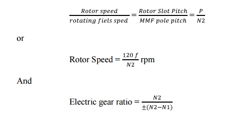
The rotor
speed is independent of the number of poles of the machine when the speed of
rotating magnetic field is reduced by increasing the number of poles of the
machine. It cannot be expected that the speed of the rotor be reduced
proportionately because when P is increased the difference between N2 and N1
should also be increased, and the electric gear ratio is reduced in the inverse
proportion. Thus the rotor speed is not affected by the number of poles but
depends on the number of rotor slots.
The main
step in design is to calculate the direct and quadrature axes reactance‘s Xd
and Xq.
Xd = X1
+Xad
Xq = X1 +
Xaq
Where X1
is the stator leakage reactance and Xad and Xaq are the direct and quadrature
axes reactance of armature reaction.Xad is the ratio of the fundamental
component of reactive armature voltage, produced by the mutual flux due to the
fundamental direct axis component of armature current,Similarly Xaq is the
ratio of the fundamental component of reactive armature voltage produced by the
mutual flux due to the fundamental quadrature axis component of the armature
current, to its component under steady state conditions and at rated frequency.
Related Topics