Chapter: Mechanical : Finite Element Analysis : Two Dimensional Finite Element Analysis
Truss Element (or Spar Element or Link Element)
TRUSS ELEMENT (OR SPAR ELEMENT OR LINK ELEMENT)
Differentiate between a truss and a frame.
Truss
Only concentrated loads act.
Loads act only at the joints.
Truss members undergo only a xial deformation (along the length of the member).
Frame
Concentrated loads, uniformly distributed loads, moments, all can act.
Loads can be applied at the joints and/or in-between the joints
Frame members can undergo axial and bending deformations (translations as well as rotations).
A grid is a structure on which loads applied perpendicular to the plane of the structure, as opposed to a plan e frame, where loads are applied in the plane of the structure.
1 Derivation of stiffness matrix and finite element equation for a truss element.
There are two joints for an arbitrarily inclined single truss element (at an angle q , positive counter-clockwise from +ve x- axis). For each joint i, there are two degrees of freedom, i.e.,
a joint can have horizontal displacement u(i) and vertical displacement v(i) . Hence, for a single truss element, there are 4 degrees of freedom. The nodal displacement degrees of freedom and the nodal force de grees of freedom are shown in the following figgure.
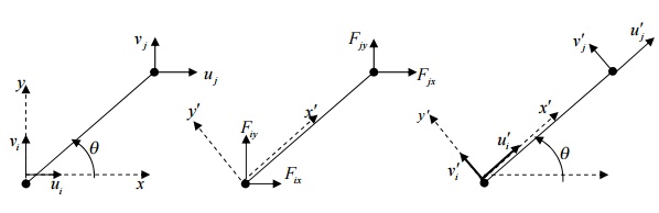
Note that the deformations occurring in the truss members are so small that they are only axial. The axial displacement of the truss can be resolved along horizontal x-axis and vertical y-axis. But in our derivation, let us resolve the horizontal and vertical displacements (in xy-axes) of a joint along and perpendicular to the truss member (in x’y-axes). Refer to the Figure in the next page. Note ui sinq component acting towards negative y -direction and all other components acting towards in +ve x - and y -directions.
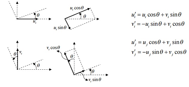
The above equations can be written in the matrix form as follows
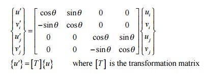
{u¢}=[T ]{u}
where [T]is the transformation matrix It is important to note that the displacements v ¢(i) and v(i) are both zero since there can be no displacements perpendicular to the length of the member. Also [T ]-1 =[T ]T
Similarly, we resolve forces along the length of the member (positive x direction) and perpendicular to the length of the member (positive y direction)
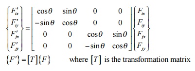
{F '}=[T ]{F }
where [T]is the transformation matrix
The arbitrarily inclined truss member can be thought of as a simple bar element oriented at the same angle q . Hence, we can write the finite element equation for this inclined bar element (in x¢ycoordinate system) as
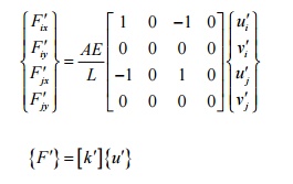
Substituting {F ¢}and {u¢}from the previous equations, we can write
[T ]{F }=[k¢][T ]{u}
Pre-multiplying the above equation by [T]-1 ,
[T ]-1 [T ]{F}=[T ]-1[k¢][T]{u}
But [T ]-1 [T]=1 and the above equation can be written as
{F }=[k]{u} where [k] [=T]-1 [k¢][T]
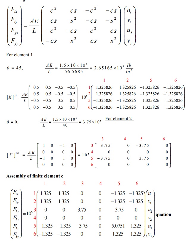
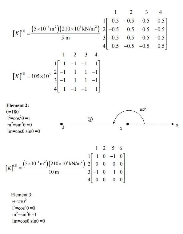
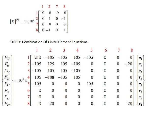
Carrying out the matrix multiplication for [k , we obtain
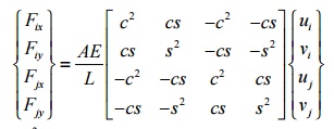
where c =cos2 q and s =sin2 q .
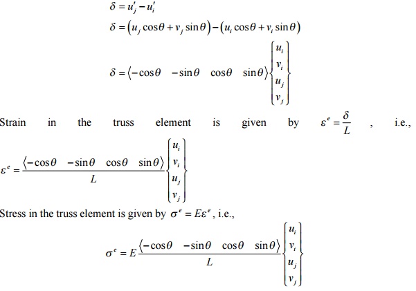
Computation of strain and stress in the truss element
The change in length of the truss member is equal to the change in axial displacement of the truss member in the x¢yco-ordinate system
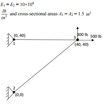
Problem
The two-element truss is subjected to external loading as shown in figure. Using the same node and element numbering as shown in figure, determine the displacement components at node 3, the reaction components at nodes 1 and 2, and the element⁶ displacement, stresses and forces. The elements have modulus of elasticity E1 = E2 = 10×106

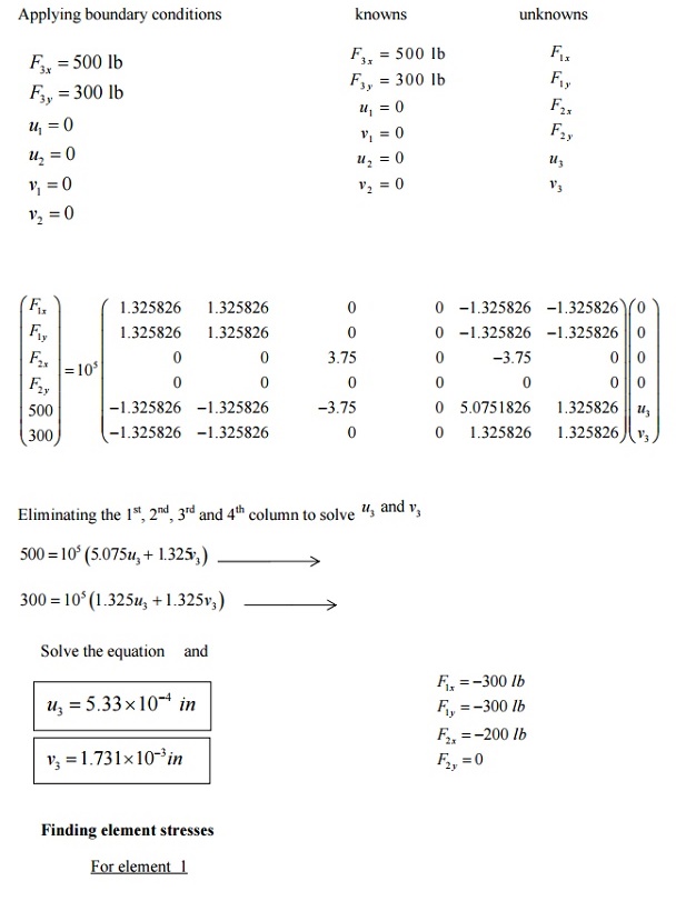
PROBLEM
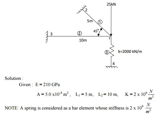
To illustrate how we can combine spring and bar element in one structure, we can solve the two-bar truss supported by a spring as shown below. Both bars have E = 210 GPa and A = 5.0 x10⁻⁴ m2. Bar one has a length of 5 m and bar two a length of 10 m. the spring stiffness is k = 2000 kN/m.
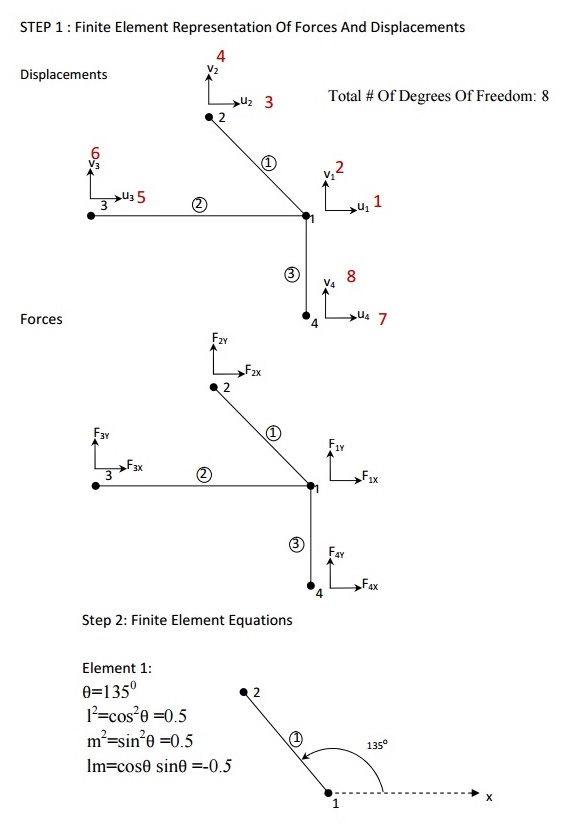
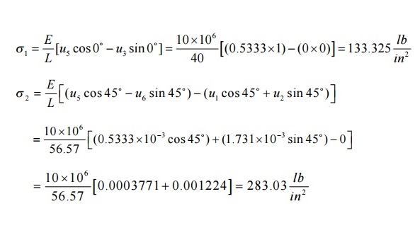
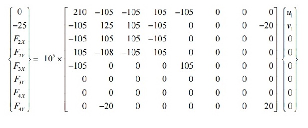
STEP 4: Applying Boundary Conditions:
Since nodes 1, 2, and 3 are fixed, we have u2 = v2 = 0; u3 = v3 = 0; u4 = v4 = 0;
F1x = 0 and F1y = -25 kN
Check whether there are as many unknowns as knowns.
STEP 5: SOLVING THE EQUATIONS:
Reduced matrix:
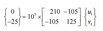
On solving,
u1=-1.724 x 10⁻³ m v1=-3.4482 x 10⁻³ m
Find the reactions at supports by substituting the known nodal values
F2x = -18.104 kN F2y = 18.1041 kN
F3x = 18.102 kN F3y = 0
F4x = 0 F4y = 6.89 kN
STEP 6: Post Processing
Stress in element 1:
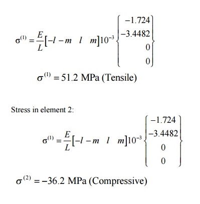
PROBLEM
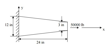
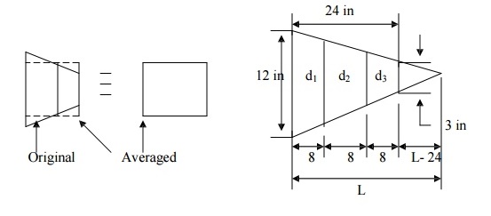
A circular concrete beam structure is loaded as shown. Find the deflection of points at 8”,16”, and the end of the beam. E = 4 x 10⁶ psi
Solution
The beam structure looks very different from a spring. However, its behavior is very similar. Deflection occurs along the x-axis only. The only significant difference between the beam and a spring is that the beam has a variable cross-sectional area. An exact solution can be found if the beam is divided into an infinite number of elements, then, each element can be considered as a constant cross-section spring element, obeying the relation F = ku, where k is the stiffness constant of a beam element and is given by k = AE/L.
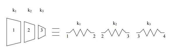
In order to keep size of the matrices small (for hand- calculations), let us divide the beam into only three elements. For engineering accuracy, the answer obtained will be in an acceptable range. If needed, accuracy can be improved by increasing the number of elements.
As mentioned earlier in this chapter, spring, truss, and beam elements are line-elements and the shape of the cross section of an element is irrelevant. Only the cross-sectional area is needed (also, moment of inertia for a beam element undergoing a bending load need to be defined). The beam elements and their computer models are shown
Here, the question of which cross-sectional area to be used for each beam section arises. A good approximation would be to take the diameter of the mid-section and use that to approximate the area of the element.
Cross-sectional area
The average diameters are: d1 = 10.5 in., d2 = 7.5 in., d3 = 4.5. (diameters are taken at the mid sections and the values are found from the height and length ratio of the triangles shown in figure 2.10), which is given as
12/L = 3/(L-24), L = 32
Average areas are:
A1 = 86.59 in2 A2 = 56.25 in2 A3 = 15.9 in2
Stiffness
k1 = A1 E/L1 = (86.59)(4 × 10⁶/8) = 4.3295 ×10 7 lb./in., similarly,
k2 = A2 E/L2 = 2.8125 ×10 7 lb./in.
k3 = A3 E/L3 = 7.95 ×10 6 lb./in.
Element Stiffness Equations
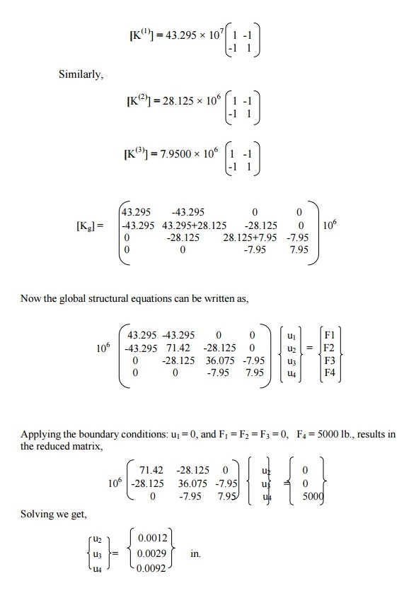
The deflections u2, u3, and u4 are only the approximate values, which can be improved by dividing the beam into more elements. As the number of elements increases, the accuracy will improve.
Related Topics