Chapter: Mechanical : Finite Element Analysis : Dynamic Analysis Using Element Method
Dynamic Analysis Using Element Method
DYNAMIC ANALYSIS USING ELEMENT METHOD
INTRODUCTION
It provides the basic equations
necessary for structural dynamical analysis and developed both the lumped and
the consistent mass matrix involved in the analysis of bar beam and spring elements.
1 Fundamentals of Vibration
Any motion which repeats itself
after an interval of time is called vibration or oscillation or periodic motion
All
bodies possessing mass and elasticity are capable of producing vibration.
2 Causes of Vibrations
o
Unbalanced forces in the machine. These force are
produced from within the machine itself
o Elastic nature of the system.
o Self excitations produced by the dry friction
between the two mating surfaces. o External excitations
applied on the system.
o Wind may causes vibrations
o
Earthquakes may causes vibrations
3.Types of Vibrations
1.According to the actuating force
Free or
natural vibrations
Forced
vibrations
Damped
vibrations
Undamped
vibrations
2.According to motion of system with respect to axis
Longitudinal
vibrations
Transverse
vibrations
Torsional
vibrations
EQUATION OF MOTION
There is
two types of equation of motion
Longitudinal
vibration of beam or axial vibration of a rod
Transverse
vibration of a beam
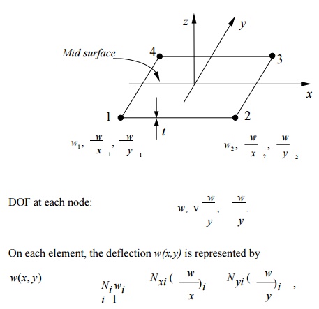
where Ni, Nxi
and Nyi are shape functions. This is an incompatible element!
The stiffness matrix is still of the form
k = BTEBdV ,
where B
is the strain-displacement matrix, and E the stress- strain matrix.
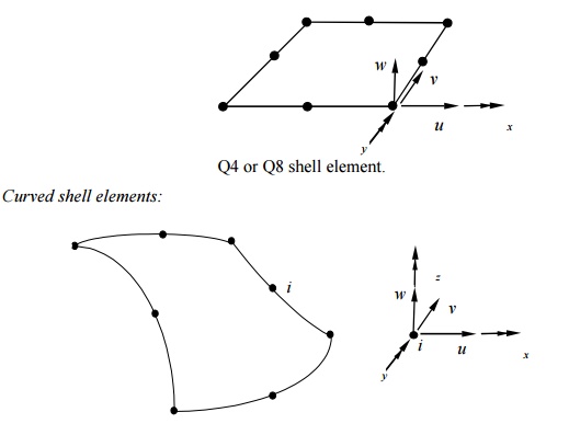
Minding Plate
Elements:
4-Node Quadrilateral
8-Node Quadrilateral
Three independent fields.
Deflection
w(x,y) is linear for Q4, and quadratic for Q8.
Discrete
Kirchhoff Element:
Triangular
plate element (not available in ANSYS). Start with a 6-node riangular
element,
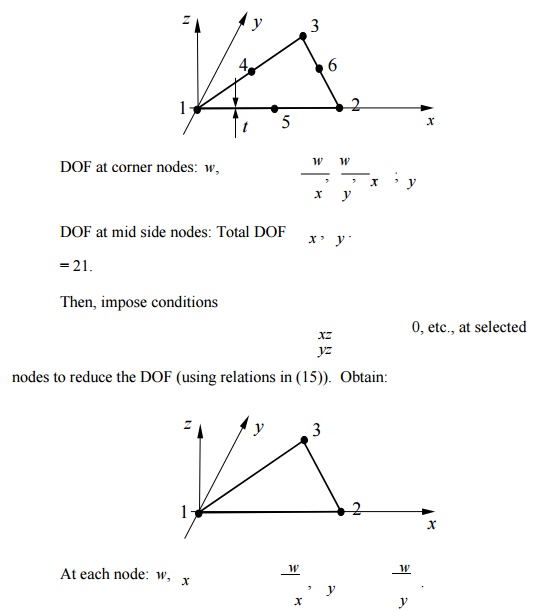
Total DOF
= 9 (DKT Element).
Incompatible w(x,y);
convergence is faster (w is cubic along each edge) and it is
efficient.
Test Problem:
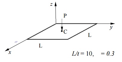
L/t = 10, = 0.3
ANSYS 4-node quadrilateral plate
element.
ANSYS Result for wc
Mesh wc
( PL2/D)
2 2 0.00593
4 4 0.00598
8 8 0.00574
16 16 0.00565
: :
Exact Solution 0.00560
Question:Converges from “above”? Contradiction
to what we learnt about the nature of the FEA solution?
Reason: This is an incompatible element ( See
comments on p. 177).
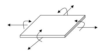
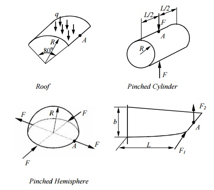
Shells and Shell Elements
Shells – Thin
structures witch span over curved surfaces.
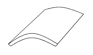
Example:
Sea shell, egg shell (the wonder of the nature); Containers,
pipes, tanks; Car bodies;
Roofs, buildings (the Superdome),
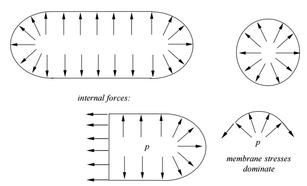
etc. Forces in shells:
Membrane
forces + Bending Moments
(cf. plates:
bending only)
Example: A Cylindrical Container.
Shell
Theory:
Thin
shell theory
Shell theories are the most complicated ones to
formulate and analyze in mechanics (Russian’s contributions).
Engineering Craftsmanship Demand strong analytical skill
Shell Elements:
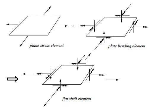
cf.: bar + simple beam element => general beam element.
DOF at each node:
Based on
shell theori es;
Most
general shell el ements (flat shell and plate elements are subsets);
Complicated
in form ulation.
Test
Cases:
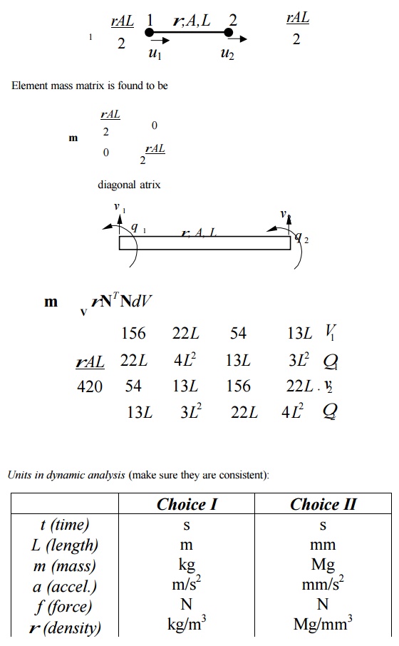
CONSISTENT MASS MAT RICES
Natural frequencies a nd modes
Frequency
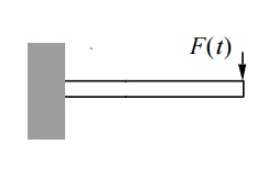
response ( F(t)=Fo sinwt) Transient
response (F(t) arbitrary)
1 Single DOF System
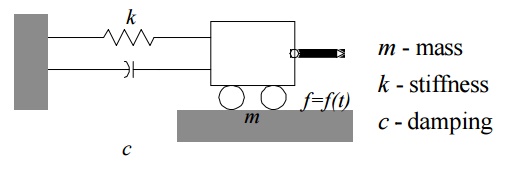
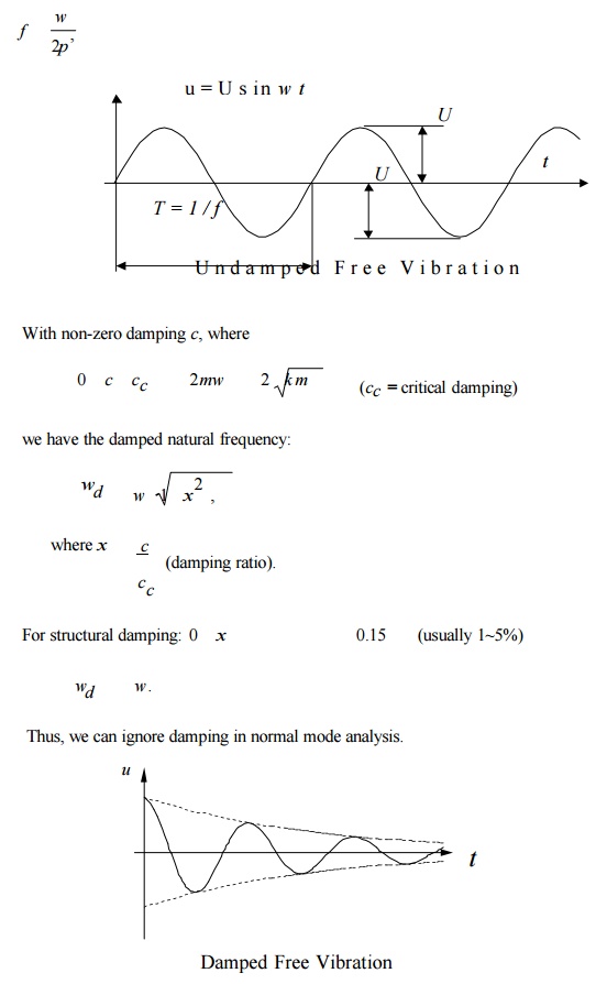
Free
Vibration:
f(t) = 0 and no damping (c
= 0) Eq. (1) becomes
mu ku
(meaning: inertia force + stiffness force = 0) Assume:
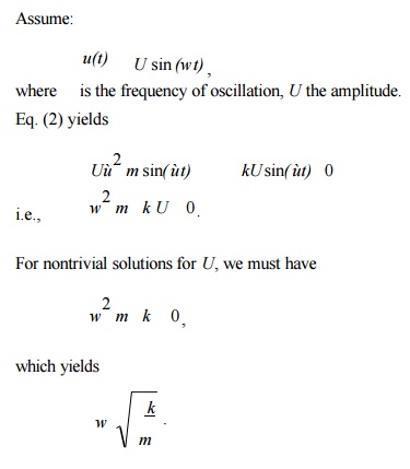
This is the circular natural frequency of the single
DOF system (rad/s). The cyclic frequency (1/s = Hz) is
2.Multiple DOF System
Equation of Motion
Equation of motion for the whole
structure is
Mu Cu Ku f
(t) , (8)
in which: u nodal displacement
vector,
M mass
matrix,
C damping
matrix,
K stiffness matrix, f forcing
vector.
Physical meaning of Eq. (8):
Inertia forces + Damping forces +
Elastic forces
= Applied forces
Mass Matrices
Lumped mass matrix (1-D bar
element):
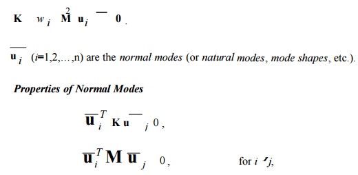
VECTOR ITERATION METHODS
Study of the dynamic characteristics of a
structure: natural frequencies normal modes shapes)
Let f(t) = 0 and C = 0
(ignore damping) in the dynamic equation (8) and obtain
Mu Ku 0
Assume that displacements vary harmonically with time, that
is,
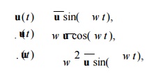
where u is the vector of nodal displacement
amplitudes.
Eq. (12) yields,
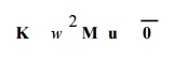
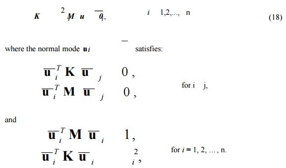
This is a generalized eigenvalue problem (EVP).
Solutions?
This is an n-th order polynomial
of from which we can find n solutions (roots) or eigenvalues
i (i
= 1, 2, …, n) are
the natural frequencies (or characteristic frequencies) of the structure (the
smallest one) is called the fundamental frequency. For each gives one
solution (or eigen) vector
if wi wj . That is, modes are
orthogonal (or independent) to each other with respect to K and
M matrices.
Note:
Magnitudes of displacements
(modes) or stresses in normal mode analysis have no physical meaning.
For
normal mode analysis, no support of the structure is necessary.
i = 0 there are rigid body motions of the whole or
a part of the structure. apply this to check
the FEA model (check for mechanism or free elements in the
models).
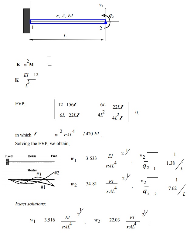
Lower modes are more accurate
than higher modes in the FE calculations (less spatial variations in the lower
modes fewer elements/wave length are needed).
Example:
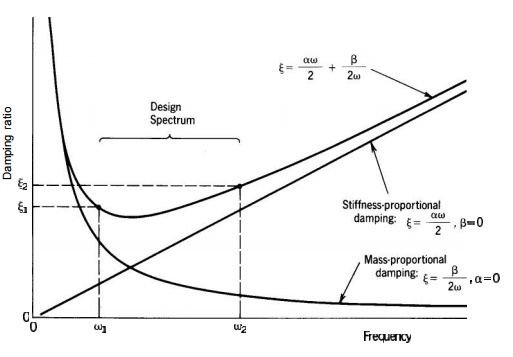
MODELLING OF DAMPING
Two
commonly used models for viscous damping.
1
Proportional Damping (Rayleigh Damping)
C M K
(17)
where the constants
& are found from
1,2 , 1 & 2 (damping ratio) being selected.
Modal
Damping
Incorporate
the viscous damping in modal equations.
Modal
Equations
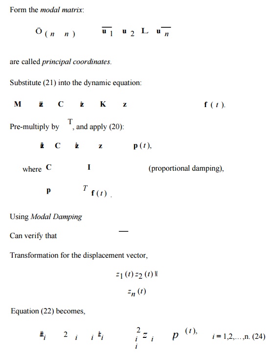
Use the normal modes (modal matrix) to transform the coupled
system of dynamic equations to uncoupled system of equations.
We have
Equations in (22) or (24) are
called modal equations. These are uncoupled, second-order differential equations,
which are much easier to solve than the original dynamic equation (coupled
system).
To recover u from z, apply transformation
(21) again, once z is obtained from (24).
Notes:
Only the first few m odes may be needed in constructing the
mod al matrix (i.e., could be an n m rectangular matrix with m<n). Thus,
significant reduction in the
size of
the system ca n be achieved.
Modal equations are best suited for problems in which higher
mode s are not important (i.e., structural vibrations, but not shock loading).
2.Frequency Response Analysis
(Harmonic Response Analysis)
Ku E u
Harmonicloading
(25)
Modal method: Apply th e modal equations,
TRANSIENT RESPONSE ANALYSIS
(Dynamic
Response/Time-History Analysis)
Structure response to arbitrary, time-dependent loading.
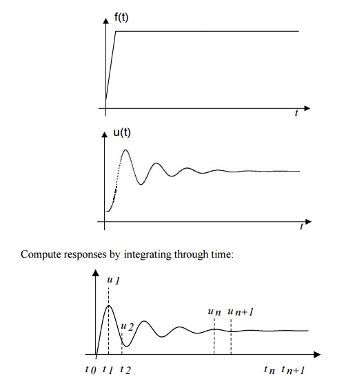
Compute responses by integrating through time:
B. Modal
Method
First, do the transformation of the dynamic equations using
the modal matrix before the time marching:
Then, solve the uncoupled equations using an
integration method. Can use, e.g., 10%, of the total modes (m= n/10).
Uncoupled
system, Fewer equations,
No
inverse of matrices,
More efficient for large problems.
1Cautions in Dynamic Analysis
Symmetry: It should not be used in the
dynamic analysis (normal modes, etc.) because symmetric structures can
have antisymmetric modes.
Mechanism, rigid body motion means = 0. Can use this to check
FEA models to see if they are properly connected and/or supported.
Input for FEA: loading F(t) or F( ) can be very
complicated in real applications and often needs to be filtered first before
used as input for FEA.
Examples
Impact,
drop test, etc.
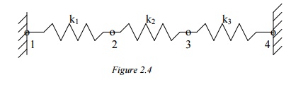
PROBLEM
In the spring structure shown k1 = 10 lb./in., k2
= 15 lb./in., k3 = 20 lb./in., P= 5 lb. Determine the deflection at
nodes 2 and 3.
Solution:
Again
apply the three steps outlined previously.
Step 1:
Find the Element Stiffness Equations
Element 1:
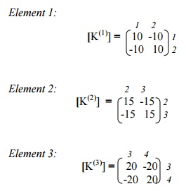
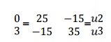
Step 2: Find the Global stiffness matrix
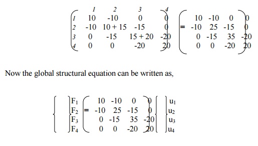
Now the global structural equation can be written as above.
Step 3:
Solve for Deflections
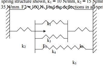
The known boundary conditions are: u1 = u4
= 0, F3 = P = 3lb. Thus, rows and columns 1 and 4 will drop out,
resulting in t following matrix equation,
Solving, we get u2 =
0.0692 & u3 = 0.1154
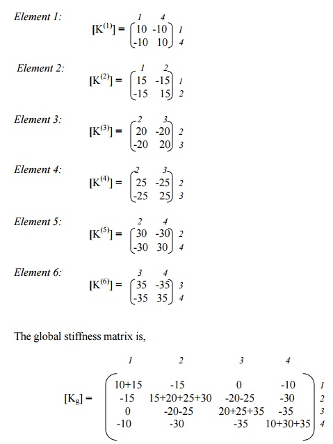
PROBLEM
In the spring structure shown, k1 = 10 N/mm, k2 = 15 N/mm, k3
= 20 N/mm, k4 = 25 N/mm, k5 = 30 N/mm, k6 = 35 N/mm. F2 = 100 N. Find the
deflections in all springs.
Solution:
Here again, we follow the three-step approach described
earlier, without specifically mentioning at each step.
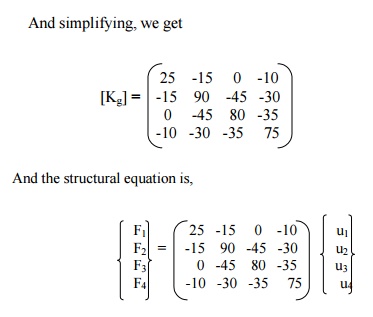
Now, apply the boundary conditions, u1 = u4
= 0, F2 = 100 N. This is carried out by deleting the rows 1 and 4,
columns 1 and 4, and replacing F2 by 100N. The final matrix equation
is,
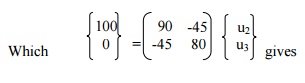
Deflections:
Spring 1: u4
– u1 = 0
Spring 2: u2
– u1 = 1.54590
Spring 3: u3
– u2 = -0.6763
Spring 4: u3 – u2 =
-0.6763
Spring 5: u4 – u2 =
-1.5459
Spring 6: u4 – u3 =
-0.8696
Related Topics