Chapter: Mechanical : Finite Element Analysis : Dynamic Analysis Using Element Method
Transient Response Analysis
TRANSIENT RESPONSE ANALYSIS
(Dynamic Response/Time-History Analysis)
Structure response to arbitrary, time-dependent loading.
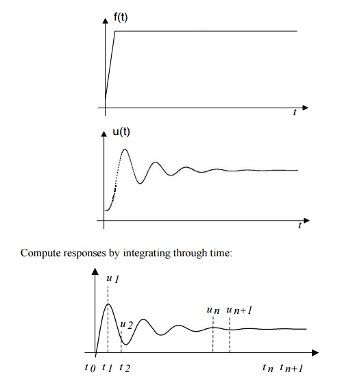
Compute responses by integrating through time:
B. Modal Method
First, do the transformation of the dynamic equations using the modal matrix before the time marching:
Then, solve the uncoupled equations using an integration method. Can use, e.g., 10%, of the total modes (m= n/10).
Uncoupled system, Fewer equations,
No inverse of matrices,
More efficient for large problems.
1Cautions in Dynamic Analysis
Symmetry: It should not be used in the dynamic analysis (normal modes, etc.) because symmetric structures can have antisymmetric modes.
Mechanism, rigid body motion means = 0. Can use this to check FEA models to see if they are properly connected and/or supported.
Input for FEA: loading F(t) or F( ) can be very complicated in real applications and often needs to be filtered first before used as input for FEA.
Examples
Impact, drop test, etc.
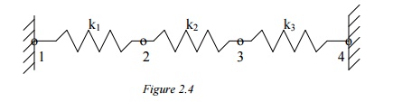
PROBLEM
In the spring structure shown k1 = 10 lb./in., k2 = 15 lb./in., k3 = 20 lb./in., P= 5 lb. Determine the deflection at nodes 2 and 3.
Solution:
Again apply the three steps outlined previously.
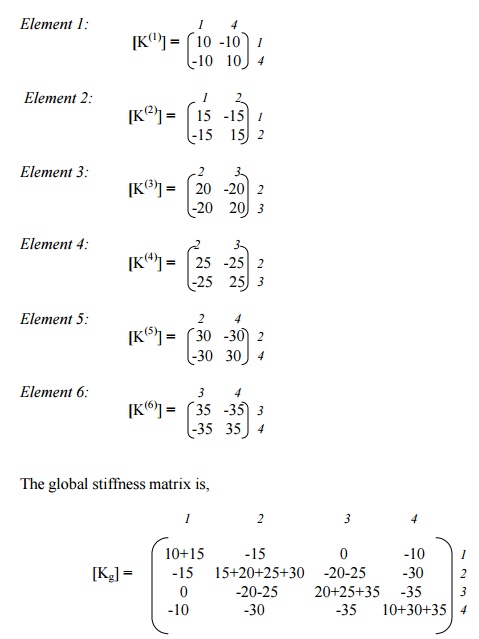
Step 1: Find the Element Stiffness Equations
Element 1:
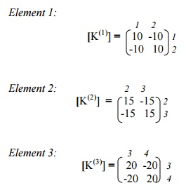
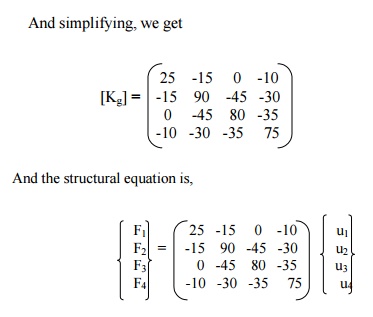
Step 2: Find the Global stiffness matrix
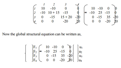
Now the global structural equation can be written as above.
Step 3: Solve for Deflections
The known boundary conditions are: u1 = u4 = 0, F3 = P = 3lb. Thus, rows and columns 1 and 4 will drop out, resulting in t following matrix equation,
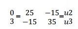
Solving, we get u2 = 0.0692 & u3 = 0.1154
PROBLEM
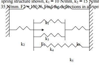
In the spring structure shown, k1 = 10 N/mm, k2 = 15 N/mm, k3 = 20 N/mm, k4 = 25 N/mm, k5 = 30 N/mm, k6 = 35 N/mm. F2 = 100 N. Find the deflections in all springs.
Solution:
Here again, we follow the three-step approach described earlier, without specifically mentioning at each step.
Now, apply the boundary conditions, u1 = u4 = 0, F2 = 100 N. This is carried out by deleting the rows 1 and 4, columns 1 and 4, and replacing F2 by 100N. The final matrix equation is,
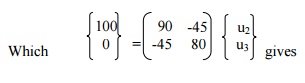
Deflections:
Spring 1: u4 – u1 = 0
Spring 2: u2 – u1 = 1.54590
Spring 3: u3 – u2 = -0.6763
Spring 4: u3 – u2 = -0.6763
Spring 5: u4 – u2 = -1.5459
Spring 6: u4 – u3 = -0.8696
Related Topics