Chapter: Mechanical : Finite Element Analysis : Two Dimensional Finite Element Analysis
Isoparametric Elements
ISOPARAMETRIC ELEMENTS
In one dimensional problem, each node is allowed to move only in ±x direction. But in two dimensional problem, each node is permitted to move in the two directions i.e., x and y.
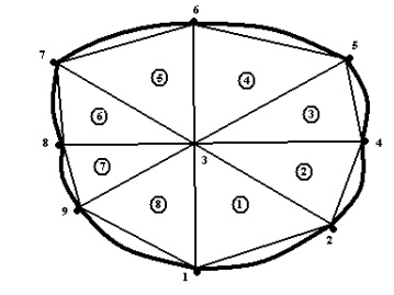
The element connectivity table for the above domain is explained as table.
Element (e) Nodes
(1) 123
(2) 234
(3) 435
(4) 536
(5) 637
(6) 738
(7) 839
(8) 931
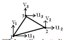
Ø Constant Strain Triangular (CST) Element
A three noded triangular element is known as constant strain triangular (CST)
element. It has six unknown displacement degrees of freedom (u1v1, u2v2, u3v3).
Ø Shape function for the CST element Shape function N1 = (p1 + q1x + r1y) / 2A
Shape function N2 = (p2 + q2x + r2y) / 2A Shape function N3 = (p3 + q3x + r3y) / 2A
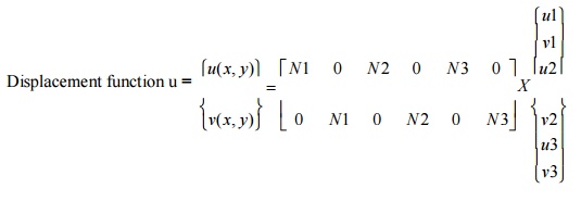
Ø Displacement function for the CST element
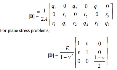
Strain – Displacement matrix [B] for CST element
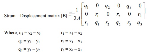
Where, q1 = y2 –y3 r1 = x3 –x2
q2 = y3 –y1 r2 = x1 –x3
q3 = y1 –y2 r3 = x2 –x1
Stress – Strain relationship matrix (or) Constitutive matrix [D] for two dimensional element
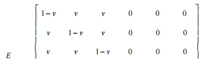
Ø Stress – Strain relationship matrix for two dimensional plane stress problems
The normal stress sand shear stresses t, t are zero.
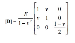
Ø Stress – Strain relationship matrix for two dimensional plane strain problems
Normal strain ez and shear strains exz, eyz are zero.
Ø Stiffness matrix equation for two dimensional element (CST element)
Stiffness matrix [k] = [B]T [D] [B] A t
For plane strain problems,
Ø Temperature Effects
Distribution of the change in temperature (ΔT) is known as strain. Due to the
change in temperature can be considered as an initial strain e0.
σ=D(Bu- e0)
Ø Galerkin Approach
Stiffness matrix [K]e = [B]T [D][B] A t.
Force Vector {F}e = [K]e {u}
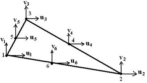
Ø Linear Strain Triangular (LST) element
A six noded triangular element is known as Linear Strain Triangular (LST)
element. It has twelve unknown displacement degrees of freedom. The displacement functions of the element are quadratic instead of linear as in the CST.
Ø Problem (I set)
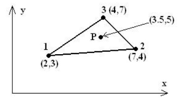
1. Determine the shape functions N1, N2 and N3 at the interior point P for the triangular element for the given figure.
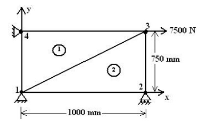
The two dimensional propped beam shown in figure. It is divided into two CST elements. Determine the nodal displacement and element stresses using plane stress conditions. Body force is neglected in comparison with the external forces.
Take, Thickness (t) = 10mm,
Young’smodulus(E)=2x10⁵ N/mm2,
Poisson’sratio(v)=0.25.
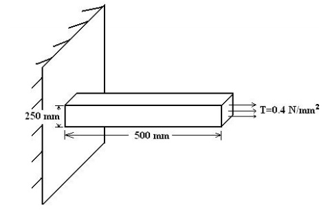
3. A thin plate is subjected to surface traction as in figure. Calculate the global stiffness matrix.
Ø Scalar variable problems
In structural problems, displacement at each nodal point is obtained. By using
these displacement solutions, stresses and strains are calculated for each element. In structural problems, the unknowns (displacements) are represented by the components of vector field. For example, in a two dimensional plate, the unknown quantity is the vector field u(x, y), where u is a (2x1) displacement vector.
3.STRUCTURAL8 MECHANICS APPLICATI ONS IN 2 DIMENSION
Elasticity equations are used for solving structural mechanics pr oblems. These equations must be satisfied if an exact solution to a structural mechanics pr oblem is to be obtained. Thest are four basic sets of elasticity equations they are
· Strain displacement relationship equations
· Stress strain relationshi p equations
· Equilibrium equations
· Compatibility equations
TRUSS ELEMENT
A truss element is defined as a deformable, two-force member that is subjected to loads in the axial direction. T he loads can be tensile or compressive. The only degree of freedom for a one-dimensional truss (bar) element is axial (horizontal) displa cement at each node.
Assumptions- Diformensional the One Truss Ele ment
Prismatic Member
The truss element is asssumed to have a constant cross-section, i.e., it is a prismatic member. If a truss structure is stepped, then it must be divided up into sectio ns of constant cross-section in order to obtain an exact solution as shown below.
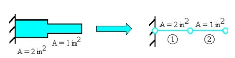
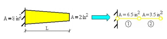
If a truss structure is tapered, then it can be approximated by using maany small truss elements, each having the sa me cross-section as the middle of the tapere d length it is approximating. The more sec tions that are used to approximate a tapered truss, the more accurate the solution will be.
Weightless Member
The weight (W) of the truss is neglected since it is assumed to be much less than the total resultant forces (F) actin g on the truss. If the weight of the truss is not n eglected, then its effects must be represented as vertical forces acting at the nodes. But sinc e truss element is defined as two-force member it cannot have any vertical (shear) force, th us the member weight has to be neglected. If shear forces exist, then a beam element must be used to model the structure.
Nodal Forces
For one-dimensional truss element, forces (loads) can only be applied at the nodes of the element, but not between the nodes. This is consistent with the FEM eq uations which relate nodal forces to nodal displacements through the stiffness matrix.
Axially Load ed
For one-dimensional truss element, forces (loads) can only be applied at the centroid of the element cross-sectional area.
BucklingEffect not Considered
A bar element can be subjected to either tensile or compressive forces. Tensile forces can be applied to a bar of any cross-sectional area or member length, and failure is associated with sudden fracture or general yielding. When compressive forces are applied to a member, it can either fail due to crushing or buckling. Buckling is present when the member bends and laterally deflects as shown on the right figure below.
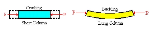
Buckling is not accoun ted for in the formulation of the truss element. Members that do not buckle are classified a s short columns and members that buckles are classified as long columns. The structural response of a short column can be predicte d with a truss element.
To determine if buckling will occur the reader should refer to a mechanics of material textbook. We will now introduce a simple geometric guideline t o determine if buckling might occur. If the ratio between the member length and the least di mension of the cross-section is equal or less th an 10, the member is considered a short colum n and buckling will not occur, i.e.,
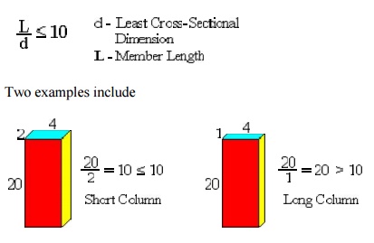
Two examples include
In the second case if a bar ele ment is subjected to a compressive force, the element will not predict the buckling response . One should note that the above geometric ru le is a simple guideline, however, in reality buckling depends not only on the member length and cross-sectional area, but material pro perties and support conditions.
Isotropic Ma terial
A truss element has the same mechanical and physical properties in all directtions, i.e., they are independent of direction. F or instance, cutting out three tensile test specimens, one in the x-direction, one in the y-dire ction and the other oriented 45 degrees in the x-y plane, a tension test on each specimen, will result in the same mechanical values for the modulus of elasticity (E), yield strength ![]() y and ultimate strength
y and ultimate strength ![]() u. Most metals are considered isotropic. In contrast fibrous materials, such as wood, typically have properties that are directionally dependant and ar e generally considered anisotropic (not isotropic ).
u. Most metals are considered isotropic. In contrast fibrous materials, such as wood, typically have properties that are directionally dependant and ar e generally considered anisotropic (not isotropic ).
Constant (St atic) Load
The loads that are applied to t he truss element are assumed to be static and n ot to vary over the time period being considerred. This assumption is only valid if the rate of change of the force is much less than the applied force (F >> dF/dt), i.e., the loads are app lied slowly. If the loads vary significantly, (i f the variation in load is not much less than the applied force) then the problem must be considered as dynamic.
Poisson'sEffect n ot Considered
Poisson's ratio is a material pa rameter. Poisson's effect is when a uniform cr oss-section bar is subject to a tensile load, and the axial stretching is accompanied by a con traction in the lateral dimension. For one-dim ensional truss element., this effect is neglected for simplicity, i.e., v = 0.
Cross Sectio n Remains Plane
For one-dimensional element, although the force(s) are acting on only the c entroid of the truss (bar) element, it is assu med that it has a uniform effect to the plane. Thus the cross section will move uniformly and remain plane and normal to the axial axis before and after loading.
Homogenous M aterial
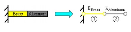
A truss element has the sam e material composition throughout and therefore the same mechanical properties at every position in the material. Therefore, the modulus of elasticity E is constant throughout the tr uss element. A member in which the material properties varies from one point to the next in the member is called inhomogenous (non-hom ogenous). If a truss is composed of different types of materials, then it must be divide up int o elements that are each of a single homogene ous material, otherwise the solution will not be exact.
The left figure shows a compo site bar composed of brass and aluminum. This structure can be divided into two elements as shown on the right, one element for the brass with E1 = 15 x 106 psi and one for the alumin um with E2 = 10 x 106 psi.
Related Topics